


Build Your First ARF
Written by Aaron Balwich Learn some basics of aircraft assembly How-to As seen in the November 2017 issue of Model Aviation.
After a modeler advances beyond a basic high-wing trainer, a more powerful, low-wing airplane is a good choice to help advance his or her skills as a pilot and explore advanced flight maneuvers. Selecting an Almost Ready to Fly (ARF) sport airplane allows a pilot to learn more about aircraft assembly, if his or her previous experience has only been with Ready to Fly (RTF) aircraft.
Let’s Get Started
The Great Planes P-51 Mustang .46-.55 GP/EP ARF has a 52-inch wingspan and is a simple, four-channel sport model that is designed for either electric power or, as in this article, a glow fuel-powered engine. The model includes all of the airframe parts and fixed landing gear, a fuel tank, an engine mount, a spinner, hardware, and an instruction manual. Other accessories are required to get it flight ready, and you’ll need a few basic hand tools to put it together. Some hobby adhesives are also required, including slow-setting two-part epoxy and CA glue. The manual should provide recommendations for adhesives. When you compare the two types of power systems, a two-stroke glow engine will require some additional field accessories, such as a glow plug ignitor and a fueling system. The P-51 comes out of the box with film covering and all of the control surfaces come already hinged in place. This model requires a four-channel radio system with four sport servos that provide approximately 54 ounces of torque. Two are required for aileron control and one each for rudder and elevator. If using glow power, a throttle servo is also needed.Radio Gear
You will need to supply your own radio. For this project, I used a Tactic TTX650 six-channel programmable transmitter and a TR625 six-channel Tactic SLT receiver. Any brand of radio gear can be used. I used standard-size Futaba and Hobbico sport servos. Because this is a glow-engine-powered model, a separate battery pack is required, along with a basic switch harness that allows the pack to be charged without removing it from the model. I’m using a 4.8-volt 2,000 mAh HydriMax Ultra NiMH battery pack. It works nicely and easily fits into place. The P-51 comes with all of the pushrod, clevis, and control horn linkage hardware, so it is easy to install and connect your servos to the control surfaces.On the Workbench
Because all of the hardware is included, you don’t have to make additional trips to the hobby shop. After opening the box and ensuring that you have everything you need, the first thing to do is to read the instruction manual. Make sure you understand the manual and have the required tools before starting the assembly. If this is your first glow-powered airplane, ask someone at your hobby shop or a local modeler for help. A few tools are needed, including a hobby knife and new blades, a pair of pliers, a screwdriver, and a tape measure or a ruler. You’ll also need some 15- or 20-minute epoxy, mixing cups, some CA glue, and spray accelerator. Following the P-51 manual, assembly begins with the wing panels. The first thing to do is to use a covering iron to remove any wrinkles from the covering. Actually, you can do this to all parts of the model. Use the string that is already taped inside of the wing panels to pull the aileron servo leads through the wing and out of the hole in the top of the wing close to the root rib. After this is done, install the servo and drill the holes for the attachment screws and screw it into place. Now remove the servo, clean away any wood dust, and apply a drop of thin CA adhesive in each of the holes. This will coat and “harden” the inside of the holes to strengthen them so you can thread the attachment screws solidly into place without them stripping out the holes.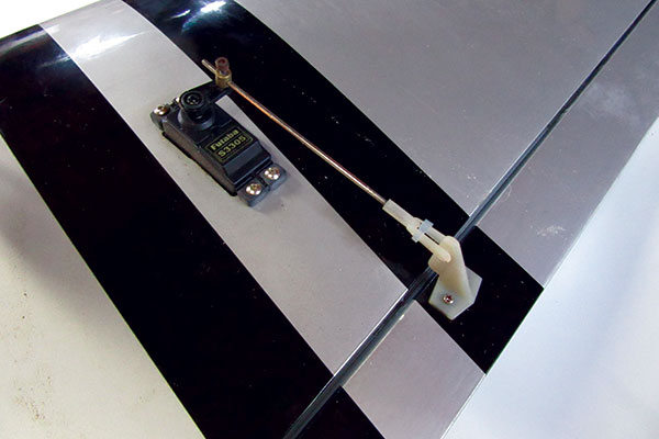
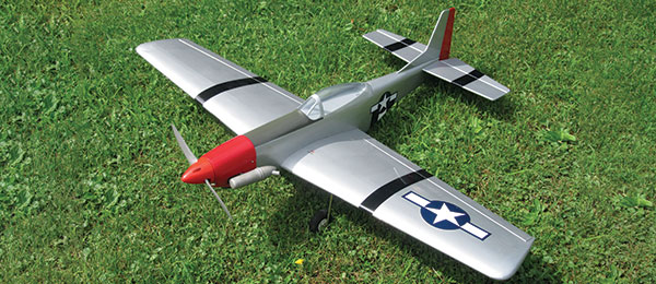
The aileron servo and control linkage are installed in the wing panel. Doing this before the wing panels are glued together makes the job easier. The author replaced the stock aileron attachment hardware with a Du-Bro E/Z Connector.
Always install the rubber grommets and the brass inserts in the servo attachment tabs. These protect the servos from vibration. The brass inserts also need to be installed to prevent the screws from crushing the grommets. Press them in place from the underside. Stack four onto a thin screwdriver, insert it into the grommet, and push the inserts in place one at a time. For models that require joining the wing panels, I have found it easier to install the aileron control horns and linkages now, before the wing is one long part. Each aileron has a control horn that is screwed into place on the bottom surface. Place the control horn on the aileron so that the holes in the arm are directly over the hinge line. Position the horn so that the linkage makes a straight line from the horn to the servo arm. Mark the aileron through the holes in the control horn and use a 1/16-inch drill bit to drill the holes all the way through the aileron. They should be square to the control surface.
The elevator control horn and the control linkage are in place. A small section of fuel tubing is used as a clevis keeper to ensure that the clevis doesn’t come loose.
Insert the screws in the base of the control horn and slip them through the holes in the ailerons. Position the backplate over the tips of the screws and tighten the screws until the plate is pulled tightly into place so that the control horn is secure and can’t move.
Servo Centering
Now you can install the servo arms. Plug the servos into a Y harness, connect them to the receiver, and switch on your radio system. Before screwing the arms into place, position them on the output shaft so that they are 90° to the servo’s centerline. When the arms are centered, thread the aileron clevis onto the wire pushrod, connect it to the aileron control horn, and mark the pushrod length at the hole in the servo arm. Now cut the pushrod roughly 1/2 inch longer. The instructions state to bend the wire pushrod 90° and use a Faslink adapter to connect it to the servo arm; however, I found that a set of Du-Bro E/Z Connectors was quicker and easier to use when adjusting the aileron center positions. The connectors simply slide into the servo arm hole and are secured with a plastic retainer that snaps into place. Slide the pushrod into the hole in the side of the retainer and a setscrew at the top of the retainer body is tightened to lock the pushrod into place. Align the ailerons so that they are even with the wing’s trailing edge (TE) at the inboard end of the aileron. With both sets of aileron linkages installed, join the wing halves by sliding the plywood wing joiner into place. The panels need to be glued together, so mix your two-part epoxy and apply a light coat to the two joiner pieces and glue them together. Add more epoxy to the outside of the joiner and the wing root rib and slide the joiner into place. Add more epoxy to the second wing panel and slide it into place over the joiner. Remember to insert the plastic alignment peg before joining the wing panels. Use some rubbing alcohol and paper towel to clean away any epoxy that drips out of the seam. Tape the two wing panels tightly together until the epoxy sets up. Make sure that the TEs and leading edges (LEs) of each panel are aligned.
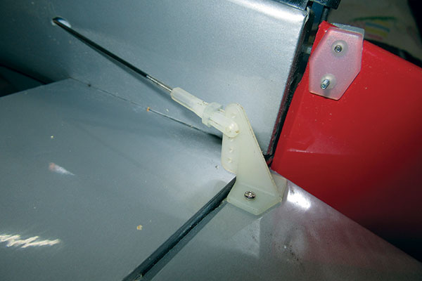
The control linkage for the rudder, elevator, and throttle are attached to the servos with Du-Bro E/Z Connectors.
After the epoxy has cured, you can install the landing gear and wheels. This model does not include retractable gear, so simply insert the gear into the slot with the vertical bend inserted in the hole in the hardwood rail. The landing gear is secured with two plastic straps that are screwed into place, centered over the horizontal gear wire. Use the holes in the straps as guides to drill the 2mm holes for the 3 x 10mm screws. If you like, you can now add the optional landing gear doors to the gear struts as shown in the instructions. They are not required, but they add to the model’s appearance. The final step is to add the front wing fairing and the aft air scoop. These are made of formed plastic. Although the instructions show them being glued in place after removing some of the wing covering, I have found that they can be glued in place with Zap Canopy Glue directly onto the covering. The glue dries clear and keeps the pieces in place. By not exposing the wood, you eliminate the chance of any fuel residue creeping under the covering at these seams. Place the wing in the fuselage’s wing saddle to align the plastic parts. This completes the wing assembly.
Tail Feathers
Cut away the spacer block at the tail of the fuselage and slide the horizontal stabilizer into place with the holes for the elevator control horn on the right side of the fuselage. Measure from side to side, making sure that the horizontal stabilizer is centered. Next, measure from the back edge of the wing saddle area to the front corners of the stabilizer and tweak the stabilizer’s position so that the measurements on both sides are the same. Use a fine-tip marker to draw some guidelines on top and bottom where the stabilizer exits the fuselage. Slip the vertical fin into the top slot and again mark some guidelines. Remove the tail surfaces and the covering between the guidelines. Use a hobby knife or soldering iron to carefully remove the covering slightly inside of each of the marks, so no exposed wood shows when they are reinserted in the slots. Do not cut into the wood. Mix some epoxy and apply the adhesive sparingly to the inner surfaces in the tail slots. Slide the horizontal stabilizer into place and position it with the guidelines. Now insert the vertical fin into the top slot. Use rubbing alcohol and paper towel to clean up any epoxy that squeezes out of the slots. This also removes the guidelines for a neater appearance. Set the fuselage aside until the epoxy cures. Flex the bottom of the rudder slightly to one side, slip the top of the tail wheel wire into the slot, and install the tail wheel bracket to the bottom of the fuselage. To make the airplane easier to work on, attach the wing to the fuselage with the two larger nylon screws. Two alignment tabs (glued together) protrude from the LE alignment and they hold the front of the wing in place by sliding into an opening in the former at the front of the wing saddle. This keeps the airframe up off the workbench to minimize any hangar rash.Control Linkage
As you did with the ailerons, install the control linkage for the elevator and rudder by first installing the control horns and placing the servos in the fuselage. Drill the servo attachment screw holes, apply thin CA glue, and screw the servos into place. Connect the servos to the receiver and switch on the radio and receiver to center the servos. Thread the clevises onto the long wire pushrods and slide them into the guide tubes in the fuselage. I used Du-Bro E/Z Connectors on the servo arms. Slide the pushrods into the connectors, center the rudder and the elevator, and tighten the setscrews at the top of the connectors. Before installing the throttle linkage, you have to install the engine.Engine Installation
The included engine mounts are molded in two pieces so that they can be adjusted for the width of the engine you are using. Slip the two halves together and lightly screw them to the firewall with the included screws and hardware. Insert the engine between the two mount rails, adjust the width, and tighten the screws holding the mount to the firewall. Slide the engine forward so that the distance between the propeller thrust washer and firewall is 41/8 inches. Mark the holes’ positions in the engine attachment tabs. Drill the four holes in the mount rails with a 7/64-inch drill bit and thread the holes with a 6-32 tap. Screw the engine in place using the four included No. 6 32 x 1-inch screws and No. 6 flat washers. Install a Du-Bro E/Z connector to the engine’s throttle arm at the carburetor and position the servo arm for the throttle so it is in line with the servo, with the transmitter’s throttle stick in the center position. Now slide the throttle pushrod wire through the E/Z Connector at the carburetor and slide it into the guide tube all the way back to the throttle servo. Use another E/Z Connector to connect the pushrod to the servo arm. Before tightening the setscrew, bring the throttle stick all the way back to idle and move the throttle trim all the way back. Now push the control linkage all the way back so that the carburetor is fully closed and tighten the setscrew at both the servo and the engine’s throttle arm. The throttle servo travel can be adjusted later before running the engine.Radio, Tank and Cowling Installation
The radio and fuel tank installation is easy because there is a removable top hatch that opens the fuselage from the firewall back to behind the canopy. After you assemble the fuel tank (using a two or three-line system), you can insert it at the front of the radio compartment, just behind the firewall.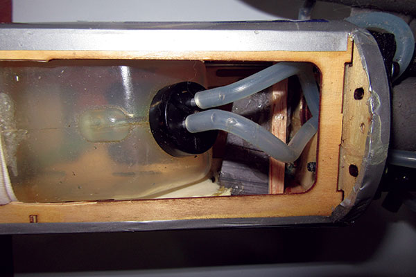
The fuel tank has been assembled and installed. The fuel line exits the firewall through the large opening and comes out under the engine.
Install the receiver in front of the servos on the platform with some foam taped around it to protect it from engine vibration. Connect the servos to the receiver and install the radio power switch in the side of the fuselage. Install the battery pack behind the fuel tank and wrap it with foam. After this is complete, reinstall the hatch cover and add the engine cowling. Before installing the cowling, trim it so that the engine head and the needle valve clear the cowling without rubbing or chafing. Center and align it with the spinner attached and a 1/16-inch clearance between the two then screw the cowling in place with two screws on each side.
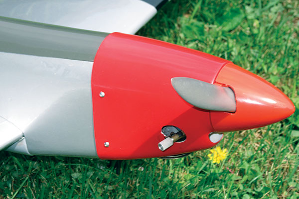
When you install the engine cowling, make sure that you leave some clearance between the cowling and the spinner.
Flight Preparation
The most important thing left to do is to balance the model. The instructions state that the center of gravity (CG) balance point should be 31/2 inches back from the wing’s LE, measured at the fuselage sides. Place some tape on top of the wing and use a pen to mark the balance point. Turn the fully assembled airplane upside down and balance at these points with your fingertips. A more precise way to check the balance point is with a Great Planes CG Machine. To adjust the CG, you can add stick-on weights in front of the fuel tank. If the model is too nose-heavy, add a weight under the horizontal stabilizer.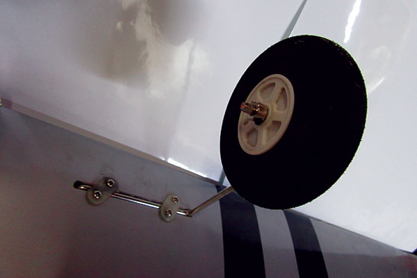
The main landing gear is shown installed. Straps screwed into place hold the gear in the attachment block that is built into the wing. Be sure to add a drop of threadlocker to the setscrews that hold the wheel to the axle.
Moving the CG forward will improve the model’s control smoothness and stability, but the aircraft will tend to be less aerobatic (which is ideal for less-experienced pilots). Moving the CG aft makes it more maneuverable and aerobatic for advanced pilots. Using your radio’s programming menu, set up your high and low rates for the control throws. The last thing to do before flying the aircraft is to adjust and set the end points for the throttle control. Start at the 100% throw setting and check the operation of the throttle and the carburetor. With the throttle and trim pulled all the way back, the carburetor should be fully closed. When you fully advance the throttle, the carburetor should be all the way open and there should be no binding causing the servo to buzz. If the travel is too much, you can move the control linkage to a hole closer to the servo output shaft or you can adjust the servo travel percentage (on the high end) in the radio. When properly set up, with the throttle trim centered, you should be able to start the engine with the throttle stick in the idle position and run it to full power. To shut the engine down, reduce the throttle setting to idle and lower the trim until the engine stops running. It might take a little adjustment with the engine running, but you need a smooth and reliable throttle response.
Conclusion
That’s it. To be successful, you have to properly assemble the model and set it up correctly. Then concentrate on improving your flight skills without having to constantly add flight corrections. —Aaron Balwich [email protected]Sources:
Great Planes (217) 398-8970 www.greatplanes.com Du-Bro (800) 848-9411 www.dubro.comThis Month's Issue

Join the AMA
![]()


1 comments
Building vs Assembling
Add new comment