


Mike Hausner's Torpedo
Written by Mike Hausner
Build your own foam fun flyer
Consruction article
Photos by the author
As seen in the December 2016 issue of Model Aviation.
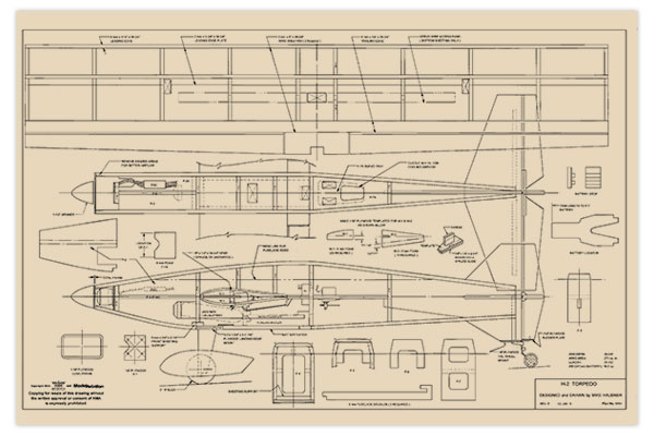
Order Plans from AMA Plans Service
|
|
 |

Specifications
Skill level: Intermediate Construction: 3mm and 6mm Depron foam Wingspan: 38.75 inches Wing area: 271 square inches Length: 31.5 inches Weight: 16.5 ounces without battery Needed to complete: Brushless motor; 6 x 4 or 7 x 4 propeller; ESC; 3S 1,320 to 2,200 mAh LiPo battery; four-channel receiver; four micro servos; one sheet each of 6mm and 3mm Depron; one sheet of 1/8 x 12 x 12 light plywood; one piece of 1/64 x 12 x 12 light plywood; three pieces of 1/8 x 1/4 x 36 spruce or basswood
Construction article
This model was originally intended to be a float model called the Lake Ontario Torpedo. I decided to test the design on wheels and then add floats, but we sold our place on Lake Ontario, so I lost my place to fly off of water. Now the airplane is simply called the TORPEDO, and it’s on wheels. This is the second aircraft I have designed to be built almost entirely out of Depron foam. If Depron is unavailable, see the “Sources” section for foam alternatives. The purpose of this design is to construct a sport/Pylon racer with a built-up symmetrical wing. I used methods similar to traditional balsa construction, but without the open framework that requires covering with plastic film. The design idea started when I sketched a model with a cuneiform tail (as much vertical fin below the stabilizer as above). I also liked the idea of a “zero-zero-zero” incidence for thrust, wing, and stabilizer. This setup would offer an airplane that would fly like crazy, easily fly knife-edge, recover from spins, and not change pitch as much with throttle changes.
Flying
The first prototype used an E-flite 1,360 Kv 370 outrunner on a 1,320 mAh three-cell LiPo battery with a 7 x 4 propeller. On the first and second test flights, the performance was not spectacular, but I only wanted to prove that it would fly. You have probably heard this before, but it practically flew right off the drawing board! By keeping the tail planted with up-elevator, taxiing was controllable, but because it had so much side area, it wanted to weathervane. Once it was pointed into the wind and the throttle advanced, the TORPEDO was soon airborne. A couple of clicks of aileron later, it was flying hands off. Loops were easy—even slightly slow. Rolls were slower than I expected. The airplane was easy to stay ahead of. I cut the throttle and the TORPEDO entered into a mild dive; I applied full throttle and it was flying level again. Level flight could be achieved at anything higher than half throttle. I changed to the recommended 8 x 4 propeller for the third flight. This dramatically altered the flight performance. Loops were easier to perform, rolls were crisp, and the model was faster, but still easy to stay ahead of. For the second prototype, I used a 2,200 Kv outrunner with a 6 x 4 propeller and a 2,200 mAh three-cell LiPo battery. This setup required some redesign to accommodate a larger battery.

The first and second TORPEDO prototypes are ready for a day at the flying field.
The new combination woke up the TORPEDO. Loops were big and round. Rolls were superfast. What a change in personality. Basic handling of the model was the same, except everything happened faster. I am delighted with the looks and performance of this design. Build it with either motor combination and you will be pleased with the results.
Building the TORPEDO
The TORPEDO is mostly a self-jigging assembly, much like a laser-cut kit. Assemble with contact cement except where epoxy or CA glue is noted. Use care in cutting out the parts and laying out the locations of the formers and ribs. I like to cut out all of the parts for the airplane before starting construction. That way everything is ready when needed. Lay out the larger fuselage and tail parts first and use a light spray coating of 3M 77 adhesive to keep the patterns in place while cutting. The leftover pieces are used for the wing ribs, formers, and other small parts. Because you have to cut out a lot of wing ribs, it is best to make a template for W-1A and W-1B as shown on the plans. Note that W-1B has a “top” because of the 90° angle at the trailing edge (TE). Mark each with an arrow.

See the sketch on the plans to make plywood templates for the wing ribs.

All of the parts for the second prototype are cut out and ready for assembly.
Building the Wing
The wing will be needed for the fuselage construction and it is the hardest part of the build, so let’s get that done first. Start construction with the upper and lower wing spars. These are made up by epoxying a 1/8 x 1/4 x 39-inch spruce or basswood stick to the straight edge of a sheet of 6mm-thick Depron foam. If you can only find 36-inch sticks, buy an extra one and add the 3-inch piece. Make sure this assembly is straight and flat! After the epoxy has cured, cut the foam along the spruce stick. Make two of these. To make the leading edge (LE), lay out the wing rib and spar locations on a piece of 3mm-thick foam sheet measuring 2 x 39 inches. Epoxy one of the wing spar assemblies to the foam sheet. Again, keep it flat and straight. After this has cured, use contact cement to install the 10 W-1A LE ribs to the sheet. Allow this to cure sufficiently and repeat for the other side of the foam rib sheet. After this assembly has completely cured, carefully sand the LE so that all of the ribs and the 3mm sheet are even, then glue on the 6mm x 1/2-inch x 39-inch foam LE. When this has cured, bevel the LE strip to match the rib profile.

This shows the completed LE rib section with the 6mm x 1/2-inch foam LE strip.
On a 3mm x 6-inch x 39-inch Depron foam sheet, lay out all of the rib and spar locations. To make the LE assembly easier, roll a slight curve to the sheeting from the spar to the LE using a 3/4-inch dowel or broom handle. While you are at it, roll the LE of the top sheeting, too. Cut out the servo wire access strip, mark its location, and save for later use. Start the main wing assembly by installing the 3mm x 3/4-inch TE strip to the bottom sheeting. Next, glue 10 W-1B wing ribs in place. Note the relief cut in the ribs that are over the servo lead access area. Keep the TE section flat against the building board until the adhesive has fully cured. At the aileron servo access area, install 3mm x 3/8-inch strips between the ribs to support the servo lead access cover. The LE rib assembly keys into the main wing assembly. To install this, I used a combination of 30-minute epoxy at the spar/sheeting contact area and contact cement for everything else. Do not glue the sheeting to the LE ribs at this time; support or tape it in place for now. Keep the LE rib assembly tight to the TE assembly and the TE assembly tight to the building board. Support the LE in its position. When the spar/rib assembly is firmly glued to the TE section, you can remove the wing from the building board. Use contact cement to glue the LE rib/spar assembly to the rest of the bottom sheeting. Taper the TE to meet the lower sheeting. Keep the wing arrow straight—no washout or twist. Install five CA hinges for each aileron. Let this assembly cure overnight and install the top sheeting using epoxy at the main spar and contact cement for everything else. When this is complete, sand the wingtips to remove any overhanging spar or sheeting material. The wingtip will be used to mark the wing cutout on the fuselage sides.
Firewall Assembly
Assemble the front firewall section first. This consists of F-1, F-1A, F-2, F-3, F-3A, F-4, the bottom sheeting support, and the battery block. Lay out the motor mount and install four 4-40 blind nuts on F-1. Cut a notch in F-1 to allow clearance for the motor wires. Assemble all of the foam parts. When the glue has sufficiently dried, epoxy F-1 to the firewall assembly and F-1A. Set it aside to cure.
Vertical Fin Assembly
From the fin, remove the area for the lower fin reinforcement. Part of this will be glued to the reinforcement. Use the 1/8 x 1/4-inch spruce or basswood leftover from the wing spars. Cut two pieces 2-15/16 inches long and epoxy them together forming a 1/4-inch-square post. In turn, glue this to the lower fin along with a section of 6mm foam to fill out the fin assembly.
Stabilizer Assembly
The horizontal stabilizer also has an added spar reinforcement. This is a piece of the same 1/8 x 1/4 stock that was used for the wing spar. Cut a 10-1/2-inch piece and taper the ends. The spar should line up with the lower fin reinforcement post. Cut a groove 3/8 inch from the hinge edge to match the length of the stabilizer spar. Glue it in place with epoxy. An easy way to cut this groove is to make a sanding block. Use a piece of the same 1/8 x 1/4-inch stock approximately 2-1/2 inches long and taper the ends. Carefully glue this 3/8 inch from the long edge of a piece of 1/8 x 1 x 4-inch plywood. Cut a strip of regular of adhesive-backed sandpaper and attach it to the 1/8 x 1/4-inch tapered strip. Epoxy a 1/4 x 1/4-inch elevator joiner to the elevator. After the epoxy has cured, slot the elevator for hinges and sand a V at the LE, then remove the crosshatched area. Before moving on, cut the slots and install CA hinges for the rudder and elevator.
Fuselage Assembly
Start the fuselage assembly by laying out the thrustline and all of the bulkhead locations on the inside of each fuselage side. Remember to make a right and a left side. Because this is a zero-zero-zero configuration, the motor, wing incidence, and elevator are all in line. Using your completed wing assembly, draw the wing shape on each fuselage side. The thrustline should go through the center of the wing. Add to this the 6mm x 11/4-inch TE extension and cut the pattern from the fuselage sides. Test fit and clean up any tight areas. It’s okay if it is slightly loose. Score each fuselage side using a pencil along the line shown on the plans. This will make it easier for the side to conform to the formers. Carefully flex the bend line. I like to add some strips to help align the bulkheads. This increases the gluing area and makes it easier to put things together. Make these strips between 1/4 and 3/8-inch wide and allow them to dry before adding formers. Install the firewall assembly (F-5, F-6, and F-7) to the fuselage side. When everything has cured, install the other fuselage side. Next, install the tapered servo mount (F-7A and former F-8). When everything is lined up, the fuselage tail section should be even. Now you can install the vertical fin. Note that it keys into F-8.

Install the firewall assembly and fuselage formers F-5, F-6, and F-7. Add strips to aid with former installation and increase the gluing area.
Install the control rod guides so that they come out under the horizontal stabilizer. With these glued in place, add the top sheeting. The bottom sheeting is in four parts—front, landing gear plate, hatch section, and rear.

Drill and tap the landing gear plate for #10-24 nylon screws.

Tape holds the top sheeting in place until the glue dries.
You can set up the hatch and hatch latch before installation. The latch I like to use is simple and easy to make. It relies on the friction between the tapped hole in the latch pawl and a nylon 10-24 screw. When you loosen the screw it rotates the pawl clockwise (as viewed from inside), away from the fuselage until it hits the hatch stop. Rotate the screw counterclockwise (again as viewed from inside), to tighten the screw. The friction causes the pawl to rotate and engage the fuselage. When it reaches the fuselage stop you can tighten the screw/hatch. The latch requires some 1/64-inch and 1/8-inch plywood, and a 10-24 nylon screw. There is also a piece of 1/8-inch plywood for the hatch tongue and a 1/64-inch plywood washer for the screw on the outside of the hatch.

A simple hatch/latch system works well.
With all of the sheeting installed, trim the edges flush with the fuselage sides. Trim the nose area and install your motor, propeller, and spinner. Check the clearance and centering with the fuselage and trim the fuselage front area for the plywood cowl frame. Glue the cowl frame in place and round the edges of the fuselage to match. Taper the area around the inside of the cowl frame as shown on the plans. Sand the LEs of the horizontal stabilizer and vertical fin. Fit the horizontal stabilizer and when satisfied, glue in place with epoxy. Check that the stabilizer is at 90° to the vertical fin. Cut the slots for the hinges in the elevator and rudder, and then sand the LEs to a V. Cut clearance in the rudder for the elevator joiner and test fit these pieces to the fuselage. Install the tail wheel assembly. Wheel pants are mounted with a piece of 1/8-inch plywood to keep them from rotating. I substituted a 4-40 socket-head screw for the axle supplied with the wheel pants.
Fitting the Wing
Add the center TE to the wing and fit the assembly to the fuselage. Check the tip-to-tail and horizontal alignment with the stabilizer and fin. When satisfied, tack-glue the assembly with CA and check everything again. Mix 30-minute epoxy with microballoons to form a medium thick paste. Force this into any gap in the wing joint and form a small fillet between the wing and the fuselage.
Final Assembly and Finishing
Install all of the control surfaces and check for looseness and adequate deflection. Add the control horns. Install your radio gear, motor, and ESC, and fabricate the linkage for all of the control surfaces. Trim the battery locator as needed to position the battery for balancing the model.
Painting Your Model
When using spray paint, test it on a piece of scrap. Some of the spray paints that I have used will attack the foam, especially if a heavy coat is applied. Acrylic paint works well, is inexpensive, and can be applied with a foam brush or airbrush. Clean all of the surfaces with alcohol to remove any contaminants. The third prototype was painted with spray paint. I used painter’s tape to form the sunburst design. Before taping, allow the base coat to dry for a day or two to keep the tape from lifting the base color. For the numeral 3 on the fuselage, I used tracing paper to make a stencil. The application side was sprayed with 3M 77 and positioned on the model. When the paint was nearly dry (I couldn’t wait to see the results!), the stencil was removed, leaving a nice crisp 3. This method offered better results than the painter’s tape.

The third prototype was painted with spray paint.
Test Flying
Choose an appropriate day for your first flight. I found it difficult to make the model go where I wanted it to in a crosswind using the hard plastic tail wheel used on the first prototype. On paved runways, the problem was worse. This is because the model has a lot of flat side area. The second and third prototypes used a rubber-type tail wheel. After the aircraft is pointed into the wind, plant the tail with up-elevator and slowly advance the throttle while releasing the up-elevator. Once rolling, a little up-elevator might be needed to break ground. When the model is in the air, reduce throttle to roughly three-quarters and trim for straight and level flight. Check the control effectiveness. Accelerate to full throttle—there should be little or no pitch change. Next, chop the throttle and observe. The model should enter a shallow dive. Now you’re on your own to try out your favorite maneuvers. Safe flying!
—Mike Hausner [email protected]
Sources:
AMA Plans Service www.modelaircraft.org/plans.aspx 3M (888) 364-3577 www.3m.com/3M/en_US/company-us Depron Alternatives: Model Plane Foam www.modelplanefoam.com RCFoam www.rcfoam.com Midwest Cellfoam (800) 637-6050 www.towerhobbies.com Great Planes Pro-Formance Foam (800) 637-7660 www.greatplanes.com
This Month's Issue

Join the AMA
![]()


7 comments
Wrong word used to describe tial feather surfaces.
Why use the expensive Depron
The idea is to have a model
This airplane sure reminds me
Correct word used to describe tail feather surfaces
torpedo plans
Torpedo plans
Add new comment