


Grumman Goose

Designed by Paul Kohlmann
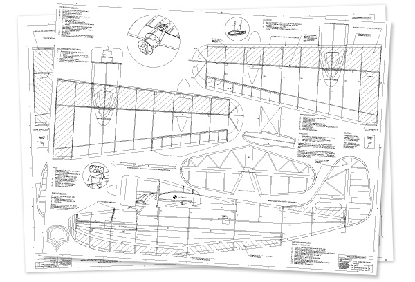
Order Plans from AMA Plans Service
 |
 |
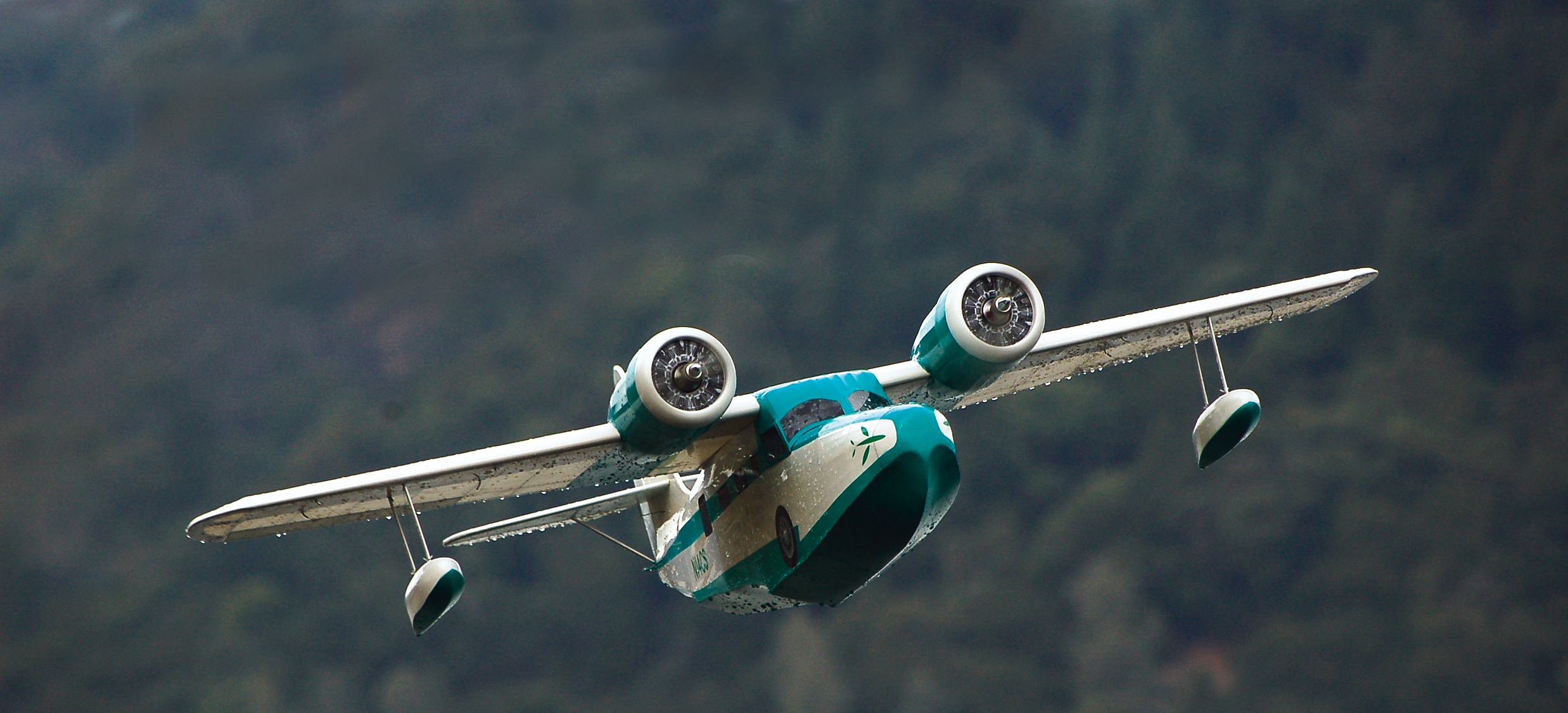
The Goose’s big rudder made lining up
photo passes such as this a breeze.
In the world of aviation, icons can be found to represent each of the categories of aircraft. For civil aviation there are the ubiquitous J-3 Cubs and Cessna high-wing aircraft, while for warbirds the P-51 Mustang is a standout.
In the RC world we often gravitate toward these iconic types, perhaps because the full-scale designs were so well developed that they tend to retain their successful attributes when scaled down for our use.
In the case of the flying boat, the Grumman Goose is one of these icons. Starting life in 1936, the first Goose was built to transport wealthy businessmen from Long Island, New York, to New York City.
By the onset of World War II, these “flying yachts” were serving more pedestrian roles with commuter airlines, the U.S. Navy, and the Coast Guard. Gooses, as Grumman called them, were flown by many nations during the war, including Japan.
Grumman stopped production in 1945 after 345 were made, but the Goose lives on. The Goose has been a staple of island-hopping, whether that is along the rugged coast of Alaska or the sunny Caribbean.
The type is so well loved that in 2007, Antilles Seaplanes announced that it would begin building new airframes to shore up the dwindling number of originals. Familiarity and longevity are critical factors in the creation of an icon, but a little limelight helps.
Hollywood has been kind, giving the Goose a central role in the TV cult classic Tales of the Gold Monkey, a cameo in the opening of Fantasy Island, and many other appearances.
Last fall I heard that MA editor, Jay Smith, was looking for a Goose design in the 48-inch range to meet a demand from AMA’s Plans Service customers.
Jumping at the chance to model an icon, I bumped the wingspan to 49 inches so that our Goose would settle in at an even 1/12 scale.
Design
I’m partial to the classic stick-and-tissue genre, and this struck me as the best way to produce a lightweight aircraft that would come off of the water easily. The design needed to build quickly and a simple, open structure supports that goal.
After studying photos and three-views, the design took root in SolidWorks CAD. The Goose has such great lines, there was no need to depart from them. I created a solid rendering by building a wireframe over a three-view drawing.
The rendering was sent to the virtual machine shop to be reduced to a framework. The power of CAD can be seen at this point as SolidWorks was able to calculate weight and CG, and configurations for hatches and such could be quickly tested.
By the time I get a design reduced to a cut file that a CNC laser can read, I’m itching to build. So let’s go!
Construction
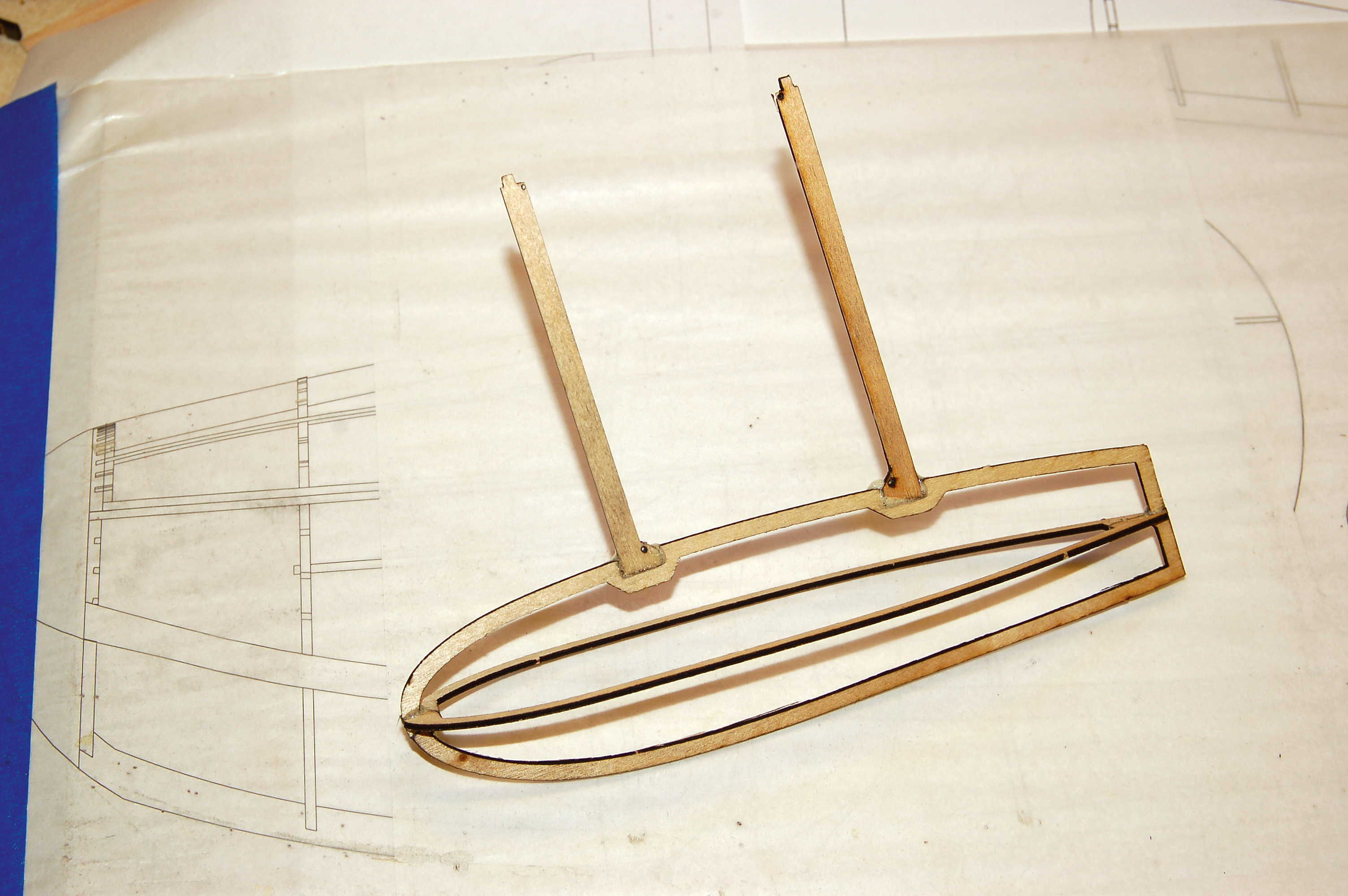
The first step is cutting forms for the three-ply laminated tail group outlines. I spray-tacked paper cutouts onto 1-inch hard foam and then cut the foam with a scroll saw.
The fin and rudder are framed
and it’s up to the builder whether
to sheet the tail or keep it at its
lightest.
Soften 1/16-inch balsa strip stock in water overnight, then pin one strip tightly against each form. Add two more layers of balsa bonded with carpentry glue to complete each outline.
Packing tape between the template and the balsa will keep the wood from sticking to the forms. Let the outlines cure completely and then pin them in place over the plans.
Glue in the 1/8-inch laser-cut tail parts in numerical order then add the 1/8 x 3/32-inch bracing. Sand the parts then cut through the outlines to free the rudder and elevators. Although the tail group is built lightly, the laminated outline provides for a strong assembly.
The horizontal stabilizer and vertical fin can be sheeted with 1/32 balsa to provide a more scale-like appearance. I went this route in order to duplicate the characteristic ribbing and trim tab on the Goose’s rudder.
To prepare the hinges, I beveled the hinge lines to allow ample elevator and rudder deflection and then installed CA hinges. In order to keep the exposed linkage to the high-mounted stabilizer short, a Sullivan rod was used to actuate a link silver soldered to the elevator joiner rod.
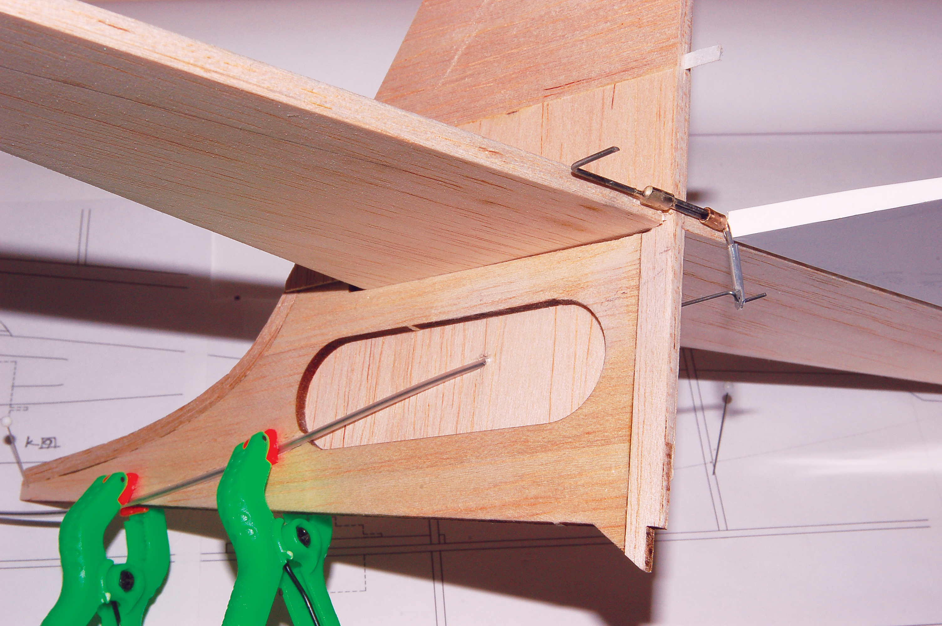
A Sullivan rod keeps the exposed elevator linkage as short as possible. CA hinges
were used for all control surfaces.
Wing
The wing is a conventional open structure with a sheeted upper LE and center section. The main spar is built from 1/8 x 3/32 balsa or basswood (depending on your flying skills!). The upper and lower main spar are constructed from full vertical-grain shear webbing.
Pin down the lower main spar and the rear spar RS, then glue in ribs W2 and W11. With these parts aligned, glue in the TE, ribs W3 through W10, the LE, and then the upper main spar.
The shear web, aileron, and wingtip parts are in place and the next step is to sheet between the main spar and the LE.
Install the laser-cut shear webs. The angle of center rib W1 determines the dihedral, so it is glued in last at an angle using a gauge.
The center wing rip is installed at an angle using a gauge to ensure that the top of the wing will be flat when joined.
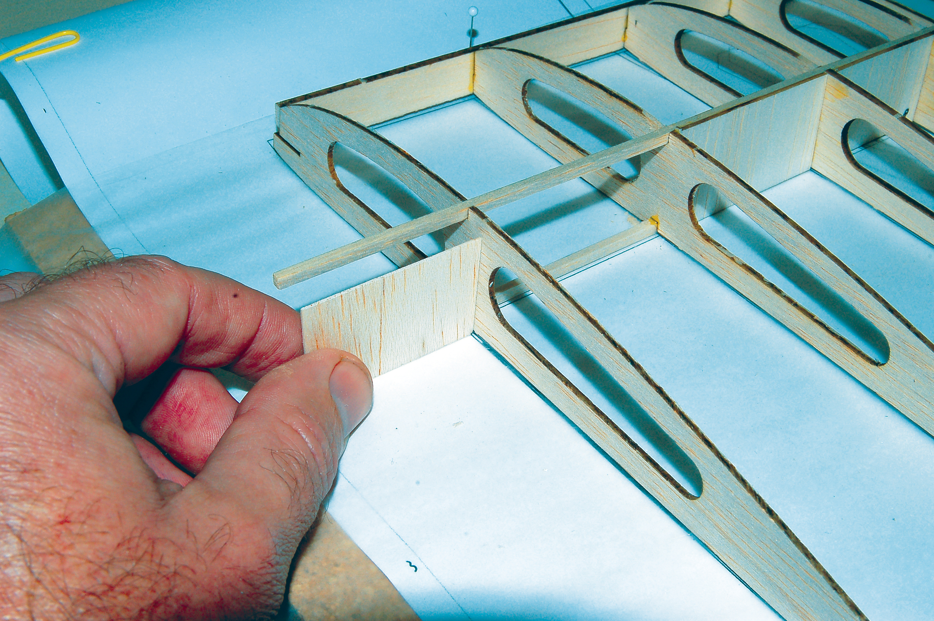
Begin the ailerons by gluing doubler A1 to the back of the rear spar with the wing still pinned on top of the plans. Pin aileron LE A2 into place but do not glue. Glue in riblets A3—they are all the same. Build the wingtip by gluing W12 through W15 in order.
I prefer to install the 1/32 balsa upper sheeting while the wing is pinned down. Dampen the outer surface lightly and it curves into place for gluing. Once cured, unpin the wing, flip it over, and sheet the lower center section. Glue in the plywood hard points for the wing floats and bracing wires.
Sand the faces of the wing roots flat and fit the plywood dihedral brace. After everything is aligned, glue in the brace and join the wings. The Goose had no dihedral so the wing will be flat across the upper main spars.
Glue soft 3/16 balsa to the face of the LE and sand to shape. Trim the LE away from the nacelle footings as shown on the plans. Complete the wing’s framework by sanding it with a long block.
After the wing is sanded to shape, cut the ailerons free by slicing through the TE. Individual aileron servos can be used to actuate them, but to avoid exposed linkages, I used a center-mounted servo and torque tubes. The torque tubes were made from .060 music wire Ls epoxied into 1/8 thin-wall aluminum tubing.
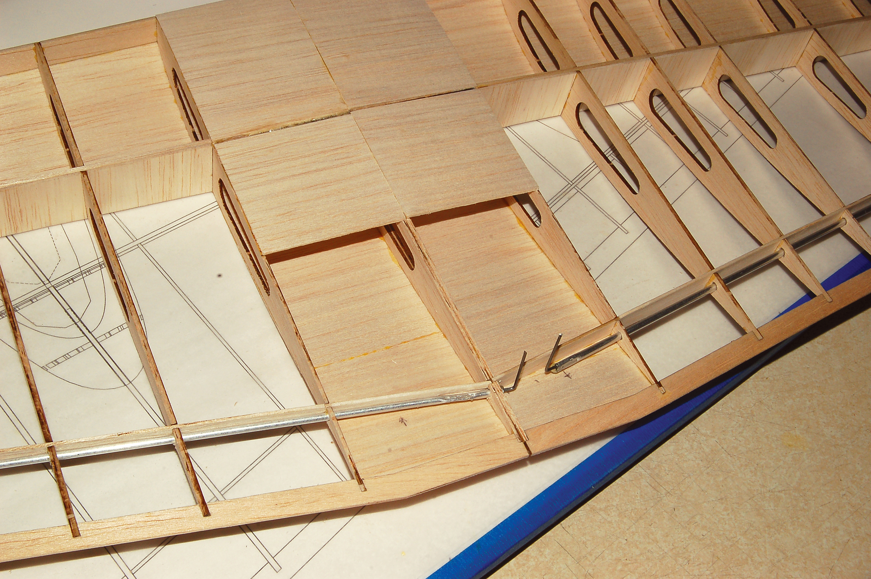
To avoid any exposed aileron linkages, a central servo was installed under the wing to actuate torque tubes made from aluminum tubing and music wire.
The wing floats are built from foam or balsa fill glued over a lasercut light-plywood framework. Sand the excess fill to shape using the framework as a template. Eyes for the bracing wires are included in the struts.
The wingtip floats are easy to shape by sanding oversized balsa or foam fi ll down to these scale plywood outlines.
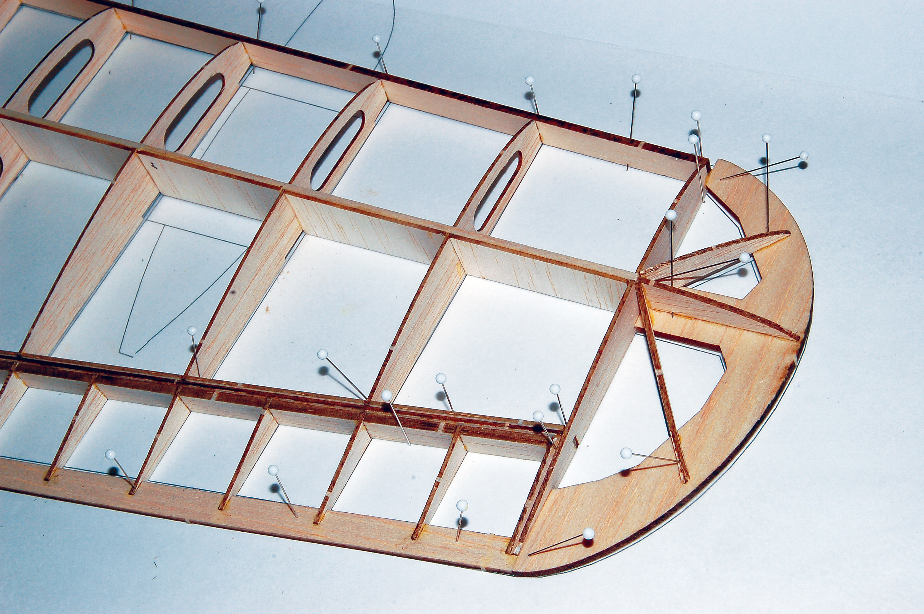
Fuselage
The fuselage is constructed using the half-shell method. Begin by pinning the keels K1 through K6 over the plans. Add the “a” or port former halves, working from nose to tail.
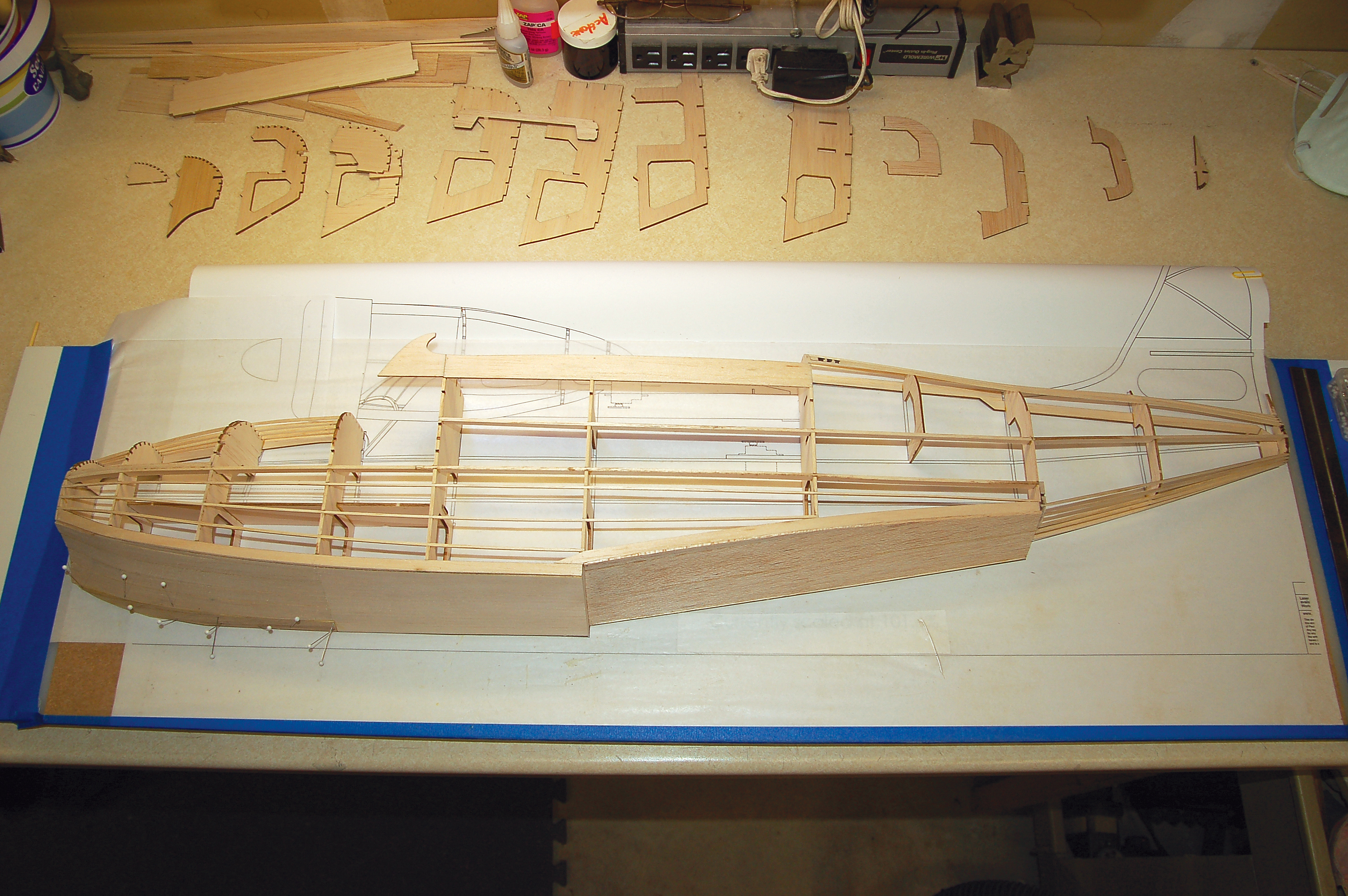
The port side of the fuselage is fi nished. When the sheeting cures the structure becomes extremely rigid.
The battery tray is locked into place by formers F2 through F5. Formers B1 and B2 are part of the battery hatch and should be glued only to keel K1 at this time.
After all of the port formers are in place, glue in side keels K7 through K10; notice that K7/8 is a longeron made by preassembling parts K7 and K8.
Glue the battery hatch side rail B3 to formers B1, F2, and B2, but be careful not to get glue on K7 or the other formers. Build up the chine by gluing in the three stringers then adding parts K11 and K12. Dampening the stringers with water before gluing into place will relieve stress in the assembly.
Attach the side wall K13s. Add enough additional stringers to give some structural integrity when the shell is unpinned.
The hull is covered by sheeting the rear sections and planking the bow. This isn’t as bad as it may sound; the sheeted areas are simple rectangles. The planked area is small and the process goes quickly if the planks are soaked in advance to soften them.
Sheeting the shell while it is pinned down ensures that the assembly will be straight when freed from the board. I debated whether to fiberglass the hull for added durability, but decided to seal it with water-based polyurethane.
The starboard half of the fuselage goes quicker. Simply unpin and repeat the steps taken so far. The servo tray can be loaded with the rudder and elevator servos and glued in now, as can partial former F5A and the wing-bolt pad. Add any remaining stringers and move on to the cockpit.
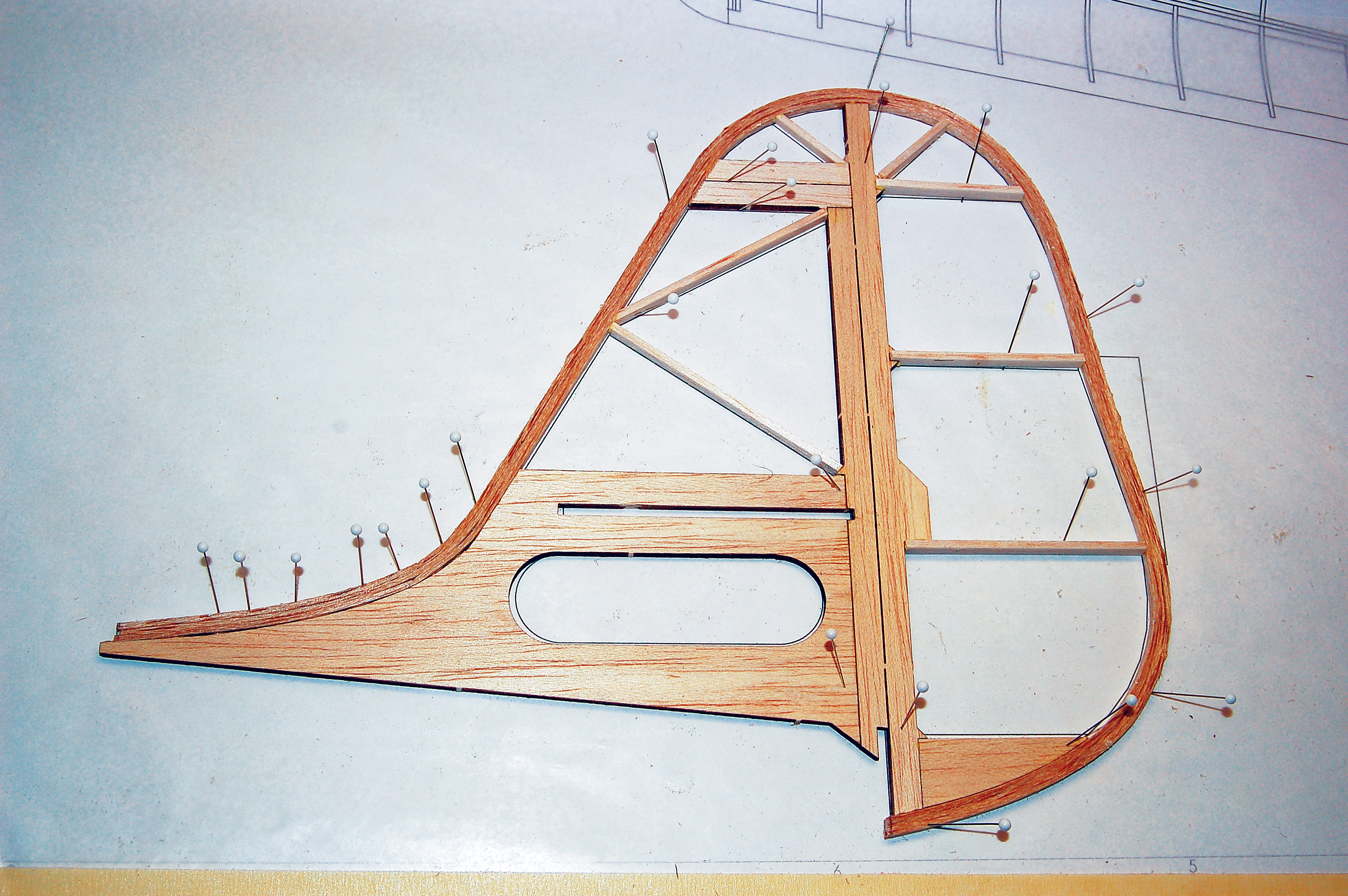
Start the cockpit by gluing ribs C2 through C4 to plywood former C1. After it is cured, slide this assembly into F5’s notches. Wet the outside of each sidewall K11, bend them into place, and glue them to C1.
Attach center rib C5 and the windshield frames to complete the structure. (Note: Covering the area under the windshield first is advisable.) Now that the cockpit is done, it’s a good time to fit the wing pin and wing bolts.
A battery hatch is designed into the upper bow. To access it, carefully cut through keel K1 and the hatch stringers between formers F1 and B1, and F3 and B2. This step can be omitted and the battery can be accessed by removing the wing if a more watertight structure is desired.
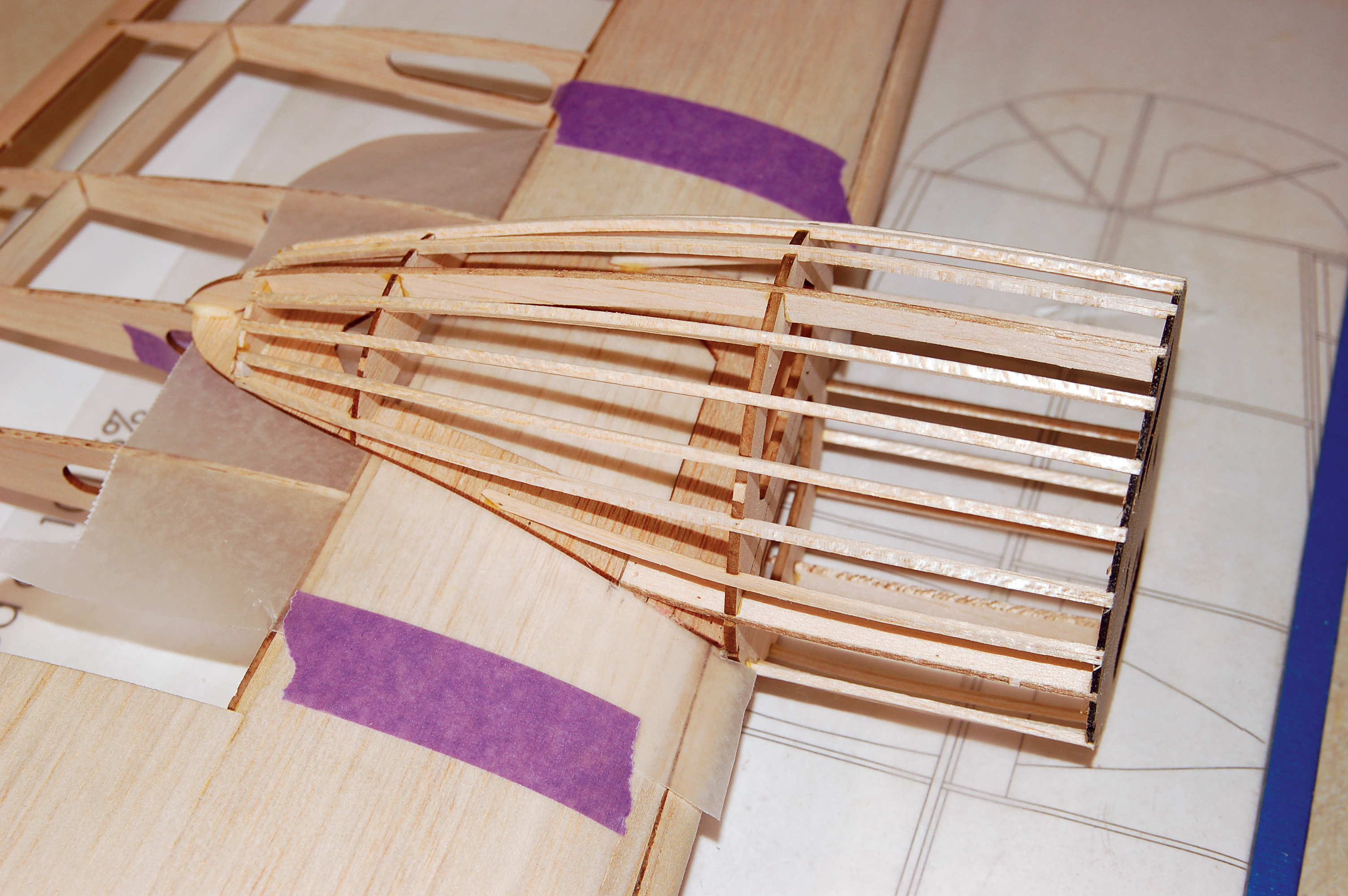
The nose is made from soft balsa and sanded to shape. Sand the fuselage lightly and it is ready to cover.
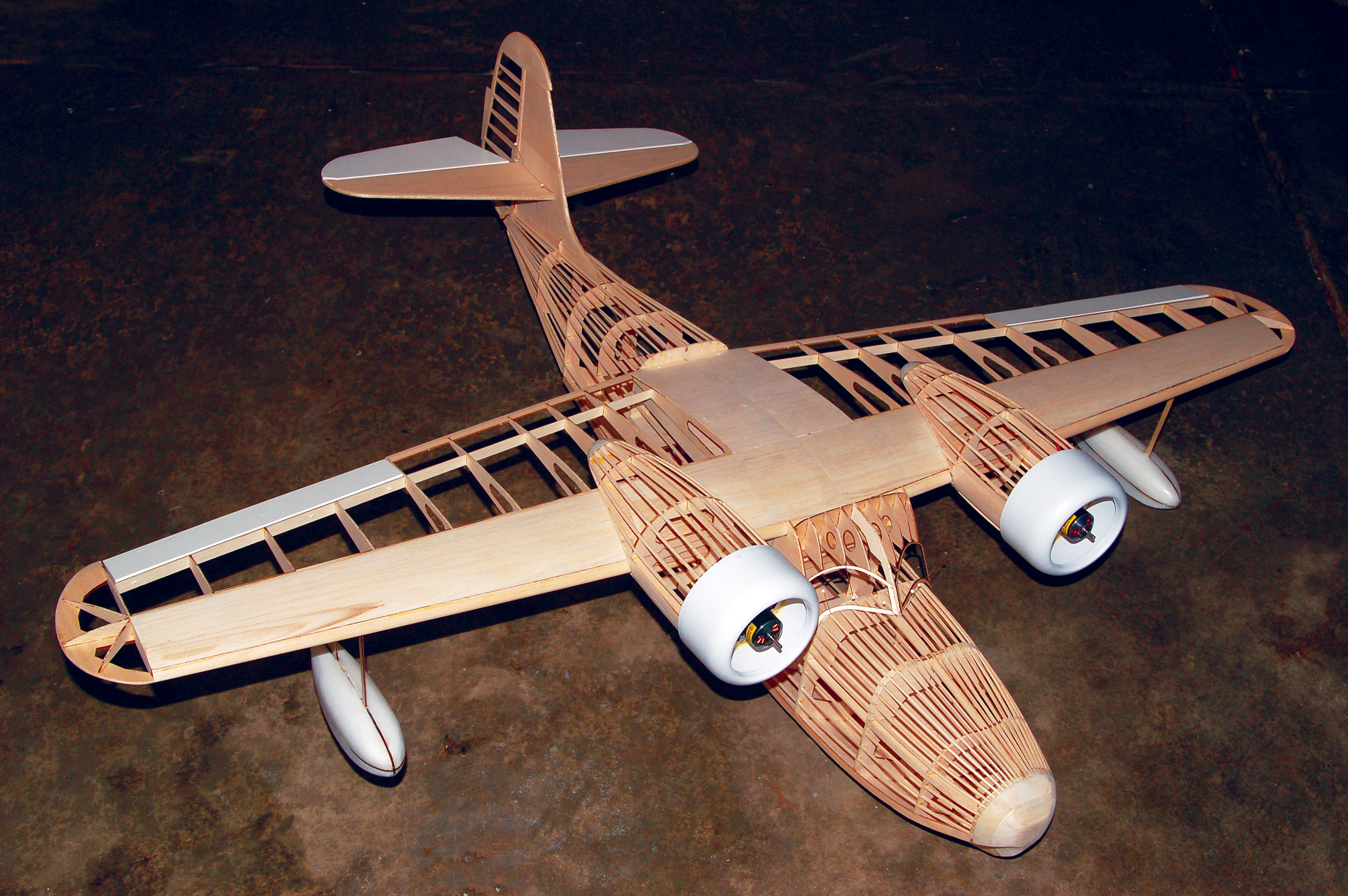
This is what the Goose looks like when there are no parts left in the kit.
Nacelles and Motors
The nacelles are designed to wrap tightly around the wing and to align themselves. Start by preassembling the upper half parts N1 through N6 over the plans. Unpin this assembly and glue in the plywood firewall and N7. Remove and discard the pad at the bottom of N4.
Join upper pad parts N8 and N9. Once dry, pin this pad to the wing with the front edge aligned to the LE. Waxed paper under the pad will prevent premature gluing of the nacelle to the wing; dampening the outside of N8/9 will help it match the wing’s curvature.
Fit the nacelle assembly to the wing with bulkhead N7 flush against LE and the three nacelle keels engaging the notches in N8/9. Glue them together when you’re satisfied they’re correctly positioned. Add bottom pad N10/11 and parts N12 and N13. Fill in the stringers to lock the pads into position.
The assembly has been glued to its pad and the lower pad, formers, and stringers are all in place. Waxed paper over the wing allows the nacelle to be removed for covering.
When everything is completely cured, pull the nacelles straight forward to remove them for covering. Use soft balsa or foam to fill the aft ends. Assemble the motor mounts from 1/8 balsa sides and plywood face. Attach them to the firewalls and the nacelles are complete.
Electronics
This Goose flew on a Hitec Micro 05S. I harvested the servos from a recently deceased ParkZone T-28. Two E-flite 370 1360 Kv motors and 20-amp ESCs powered the 8 x 6 APC propellers.
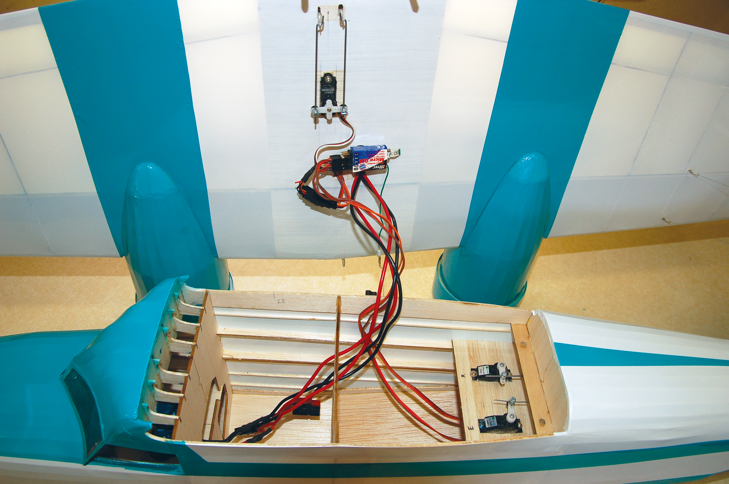
Installing the electronics is straightforward, although it’s possible I could have saved an ounce in wiring mine.
As is common with twins, the port motor turned in reverse to neutralize torque factors. This combination produced 350 watts on a 2200 mAh three-cell battery.
Finishing
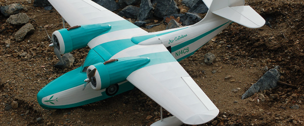
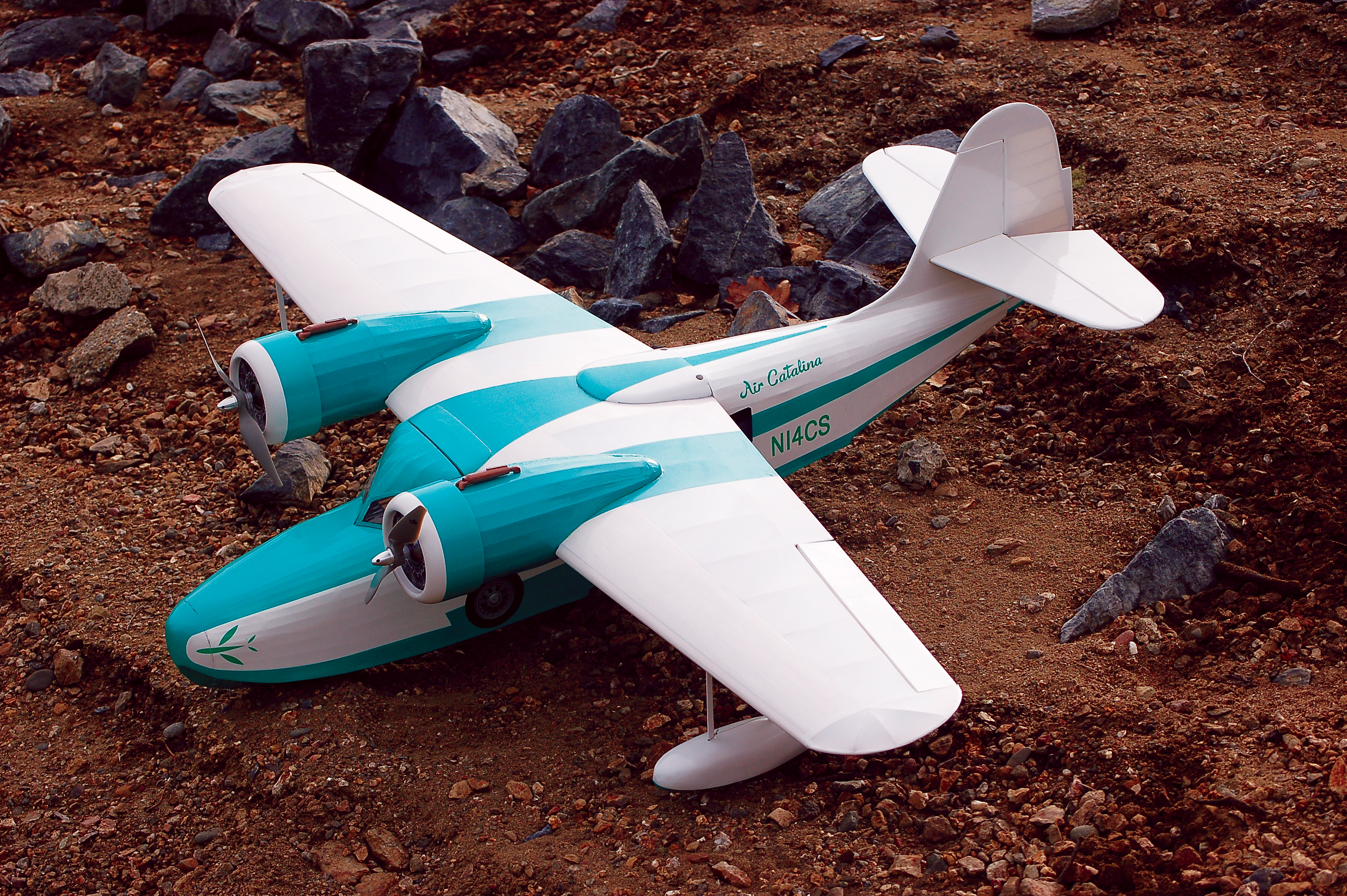
Choosing a motif for your Goose can be a challenging task. There are enough fantastic military, commercial, and private schemes to satisfy anyone’s taste. I wanted something simple using the Oracote covering that I had in my box. The teal-and-white paint scheme from Catalina Airlines of the 1970s fit the bill.
After covering, the tail was assembled by locking the fin into its notch and sliding the horizontal stabilizer through its slot in the fin. Control surfaces were mounted with CA hinges. The nacelles were epoxied onto the wing and the gaps sealed with small beads of clear silicone. After mounting the floats, they were rigged with bracing wire made from Kevlar fishing line.
I limited the details to the horizontal stabilizer struts, a pilot, and the engine exhausts, but a builder could certainly go further. I made waterslide decals for the logos, passenger windows, and a few other items.
The cowlings are vacuum-formed parts from Park Flyer Plastics. The dummy motor is a laminated photograph filling the open cowling.
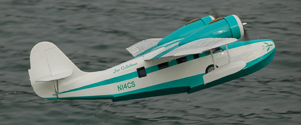
Flight Report
The Grumman Goose is ready to
get its feet wet for the first time.
The prototype weighed 37 ounces with a wing loading of only 13 ounces per square foot. The CG was set to 25% Mean Aerodynamic Chord and then the Goose was prepared for a dry maiden flight.
The initial plan was to hand launch it, but I thought I’d see if the Goose would scoot over the wet grass on the baseball field. Scoot it did—and six feet later the aircraft was airborne!
The Goose climbed out with authority, and after some down trim it was docile. The 370 motors provided plenty of power for non-scale flight but the low wing loading and high drag from the fat fuselage would let the aircraft slow down to a crawl.
For most of the flight, the Goose looked like the full-scale aircraft, flying low and slow, but the best part was the landings. After riding out the ground effect, it kissed the grass with a soft shushing sound, giving the impression that the lawn had turned to water.
Next I let the Goose loose on the lake. Although there was only a steady 5 mph wind, there was more of a wind chop than I had hoped for—particularly since that I had never flown a flying boat from water before.
Nevertheless, the Goose pushed off. Its big tail kept it tracking straight into the wind. It rode high in the water, taking the small waves well. The first attempt ended in a pirouette after I sank the left tip float before liftoff.
The next four attempts were textbook flights, after I learned to play the rudder and aileron together to get the Goose off of the tip floats during the run-up. The model is quite responsive to the rudder, making it easy to line up.
Once dialed in, rising off the water took only a few feet with a little headwind.
The wind chop proved to be no problem. Flight photos by Bingo Kohlmann.
After the routine was set, the Goose popped off the water in a few feet and then majestically climbed away, leaving a trail of water droplets behind.
The learning curve for landing was similar. I discovered that water is bouncier than grass after coming in a little too hot. Although a splash-and-go would have been prudent, I forced the Goose back down, resulting in a spectacular geyser. After applying some more patience, the next three were a piece of cake.
Conclusion
There is plenty of information here, but don’t let it scare you away from adding a legend to your hangar. This build goes quickly, thanks to a laser-cut kit, and no specialized construction techniques are required. Additionally, the power system is economical and the flying characteristics are docile.
If you have wanted to become amphibious, this Goose is a great way to go!
—Paul Kohlmann
[email protected]
Type: RC Scale model
Skill level: Intermediate builder, intermediate pilot
Wingspan: 49 inches
Wing area: 396 square inches
Length: 393/8 inches
Weight: 34 to 40 ounces
Power: Two E-flite Power 370 1360 Kv motors, two 20- to 25-amp ESC
Construction: Balsa and light plywood
Covering/finish: Heat shrink film with painted trim and waterslide decals
Propeller: Two APC 8 x 3.6
SOURCES:
Manzano Lazer Works
(505) 286-2640
www.manzanolaser.com
E-flite
(800) 338-4639
www.e-fliterc.com
Hitec RCD
(858) 748-6948
www.hitecrcd.com
Park Flyer Plastics
(817) 233-1215
www.parkflyerplastics.com
Similar Articles
 |
The Grumman Widgeon Online exclusive video interview. Jay Smith talks about the Widgeon. |
 |
Midwest Regional Float Fly Written by Jay Smith. As featured on page 20 in the May 2012 issue. Read the excerpts and online exclusive content. |
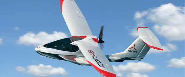 |
The Icon A5 Written by Jay Smith. Find the full feature on page 55 in the May 2012 issue. Watch a shop video and an interview with the designer |
Build This Plane!

Grumman Goose: 1/12 RC Scale float plane by Kohlmann spans 49 inches and weights 34 to 40 ounces. Plans cost $12.00 plus shipping and handling.
Begin your order by clicking a button below.


This Month's Issue
Join the AMA
![]()


30 comments
What a Plane !
Thanks very much David!
Great Model of a Great Subject
Thanks very much Cliff!
Laser cut kit
Cowl
Park Flyer Plastics
Park Flyer Plastics
Grumman Goose Build
Thanks Dr Mike!
Well Paul not sure if you
Details please!
20% off during October 2013
The retail price of the plans
Thanks
Plan for Grumman Goose
Links
Plan for Grumman Goose
Enjoy
Plan for Grumman Goose
Plan for Grumman Goose
Grumman Goose Build
Thanks, Dr. Mike!
Goose landing gear
Hi Paul,
Building the Goose
Hi Don,
Grumman Goose
Grumman Goose
Engine size?
Add new comment