


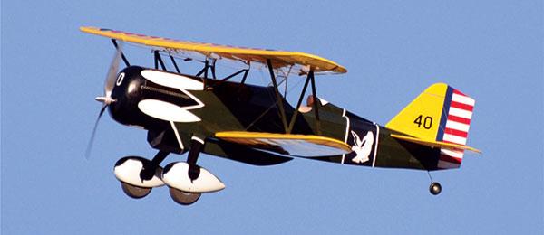
Curtiss P-6E Hawk
Written by Pat Tritle
Build this classic electric model
Construction feature
As seen in the March 2017 issue of Model Aviation.
Bonus video:
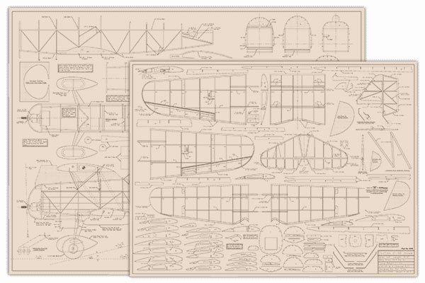
Order Plans from AMA Plans Service
|
|
 |

Specifications
Wingspan: 44 inches (top); 36.5 inches (bottom) Length: 31.5 inches Wing area: 513 square inches Flying weight: 27 ounces Wing loading: 7.6 ounces per square foot Power: Suppo 2217/9T outrunner motor; 20-amp ESC; Venom 2,000 mAh 2S LiPo battery; APC 11 x 5.5E propeller Radio gear: Two Suppo SP-90 servos (rudder and elevator); two Suppo SP-60 servos (ailerons); JR XG8 transmitter; JR RG612BX receiver
Materials List
Wood
Two 1/16 x 3 x 36-inch balsa sheets Two 3/32 x 3 x 36-inch balsa sheets Three 1/8 x 3 x 36-inch balsa sheets One 1/8 x 6 x 12-inch light plywood One 1/32 x 1 x 2-inch birch plywood Fifteen 1/16 x 1/8 x 36-inch balsa Four 1/16 x 3/16 x 36-inch balsa Five 1/16 x 1/4 x 36-inch balsa Six 1/8 square inch x 36-inch balsa Three 1/8 x 1/4 x 36-inch balsa Three 3/16 x 1/2 x 36-inch balsa One 1/4 x 6-inch balsa triangle
Tubing
One 7/32 OD x 36-inch aluminum tube One 5/32 OD x 36-inch aluminum tube One 3/16 OD x 36-inch brass tube One 1/8 OD x 36-inch brass tube One .032 ID x 12-inch plastic tube (elevator pushrod tube)
Wire
One .093 diameter x 36-inch steel wire One .046 diameter x 36-inch steel wire One .039 diameter x 6-inch steel wire One .025 diameter x 24-inch steel wire
Miscellaneous
One pair of 2.75-inch main wheels One 1-inch tail wheel Four 3/32-inch wheel collars One .008 x 2 x 5-inch acetate One manila file folder One 11-inch servo Y lead Two 4-inch servo extensions Fifteen feet of heavy-duty nylon thread Six 3/16 x .02-inch rare earth magnets One .010 x 6 x 6-inch sheet polystyrene plastic Blue foam or balsa blocks (headrest, cowl, tail fairing blocks, wheel pants, and external fuel tank)
Construction feature
A Curtiss X-P6A took first place in the 1927 US National Air Derby and Air Races with a speed of 201 mph. During its operational military history, from 1932 to 1937, the P-6E, a later version of the X-P6A, served in the 1st Pursuit Group at Selfridge Field, and the 8th Pursuit Group at Langley, Virginia. P-6s flew in several color schemes, but the most recognizable was the Snow Owl scheme of the 17th Pursuit Squadron. The full-scale Curtiss P-6E had a wingspan of 31 feet, 6 inches, and a top speed of 204 mph. Power was provided by a Curtiss V-1570-23 Conqueror liquid-cooled V-12 engine producing 700 hp and a climb rate of 2,480 feet per minute. The model was designed with a 44-inch wingspan at 1:8.6-scale for four-channel RC and electric power. The P-6E is primarily wood construction with the option of balsa or blue foam blocks to be used for the cowl, wheel pants, headrest, and other small detail parts. To allow for easy transport, the wings plug in and are removable in upper and lower pairs, and like the battery hatch, no tools are required to remove or install them. The design features basic “old-school-style” stick-and-tissue construction for the fuselage and tail group, with egg-crate-style wings for quick, accurate assembly. The wing and stabilizer tips are laminated balsa to keep with the strong, yet lightweight structure. The model is lightweight, making it ideal for small fields and parks, but with a 44-inch wingspan it’s also large enough to fly at conventional flying fields.
Tail Section
Begin by using the patterns provided on the plans to make up all of the parts required to build the model using the balsa sizes called out for each part. Bow up all of the wing and stabilizer tips by making up the bowing pattern from artist foam board using the provided patterns. If you’re new to this technique, check out the tutorial at www.patscustom-models.com/bowedoutlinres.html for the step-by-step process to make up the outlines. The vertical and horizontal stabilizers are built directly over the plans. Both the vertical and horizontal stabilizers are airfoiled, so shims are used at the leading edges (LEs) and trailing edges (TEs) to center them on the ribs. When the assemblies are complete, remove the frames from the board and sand to shape using the cross-sectional views to shape the airfoil, and then add C1 and C2, gluing them flush with the bottom surface. Cut in the hinge slots and dry fit the hinges in place. The hinges won’t be glued in until after the frames are covered.
Wing Center Section
Glue CS5 in place on CS3 and CS4 and pin them in place on the plans. Fit the ribs onto the main and rear spars and pin the assembly over the plans. Add the LEs and TEs and glue each point of contact. Remove the assembly from the board and sand to shape, then fit and glue the aluminum receiver tubes in place and sand them flush with the outboard ribs.
Top Wing Panels
Pin A5 and SM1 in place over the plans, then dry assemble the ribs onto the main and rear spars and pin them in place over the plans. Laminate A3 and A4 together and glue them, followed by the LEs and TEs, tip bows, and SM3 and SM4.

The aileron servo is glued in place with silicone caulk.
The ailerons are built directly into the wing assembly. Begin by beveling the bottom of A6 using the R5 rib detail drawing for reference. Pin A6 in the correct location over the plans and add each of the ribs and A7 to complete the basic frames. Remove the wings from the board. Score and crack A5 at the front spar to angle into the curvature of the airfoil and glue in place. Sand the wing assembly to its final shape. Cut the ailerons from the wing, sand to shape, and dry fit the hinges. Make up the brass joiner tubes and glue them in place. Fit and glue the balsa rigging blocks at R3 and drill for the flying wires. Center the servo arms on the servo, then glue the servos in place using silicone caulk. When it has dried, run in the servo wiring.
Bottom Wings
Dry assemble the ribs and spars then align and pin them in place over the plans. Add the LEs and TEs, tip bows, and strut hardpoints and glue them in place. Remove the wing panels from the board and sand to shape. Cut the brass joiner tubes to length and glue them in place as shown. Fit and glue the balsa rigging blocks at R10 and drill for the flying wires.
Fuselage
Build the side frames directly over the plans, noting the location of B3 on the right side frame only. To join the side frames, pin the frames over the plans at B1, then add the formers and crosspieces from former 6 forward. Pull the aft section together, glue the tail post together, add the remaining formers and crosspieces, and remove the frame from the board.

The cowl and headrest were made from blue foam, coated with drywall mud, then sanded smooth and sealed with two coats of water-based varnish.
Bend the landing gear to shape, lash it to the landing gear mechanism using heavy-duty nylon thread, and harden the thread with thin CA adhesive. Fit and glue the cabane mounts in place on Formers 3 and 4, and then add the aluminum receiver tubes. Laminate two sets of B1/B1A and align and glue them in place using the bottom wing to ensure proper alignment. Finally, fit and glue all of the stringers in place. Make up the servo mounts and set up the rudder and elevator servos, elevator pushrod tube, and supports. A diagram is provided to set up the continuous pull-pull rudder cables. Build up the radiator assembly and dry fit it to the fuselage. Make the cockpit fairing from file folder paper using the provided pattern and glue in place. Build up the headrest, cowl, optional external fuel tank, and tail fairing blocks from soft balsa or blue foam then sand the entire fuselage assembly to final shape.

The external fuel tank is carved from blue foam and secured to the battery hatch with magnets.
For a smoother covering job, sand a slight scallop between each of the stringers, except where the covering will attach. Build up the motor mount and dry fit the motor in place. Final adjustment will be made using the cowl to determine the proper depth and alignment before gluing in the mount.

The motor mount is fitted into the fuselage and set for proper angle and depth using the cowl to set up the alignment, and then glued in place.
Wing Struts
Bend the front and rear cabane struts to shape at the bottom only, then bend the diagonal brace and solder the struts together. Squaring blocks are used to ensure that the bottom sections of both struts are parallel.

The wings are dry fitted onto the fuselage, and necessary adjustments are made for proper alignment.
Mark the location of the top bend using the bending patterns and plug them into the fuselage. Make the top bends at the marks so that all four are parallel and perpendicular. Build the interplane struts over the plans and sand to shape. Plug in the wings and dry fit the center section using the wing-alignment jig. Adjust the struts as required for proper fit and alignment and add the balsa fairings.
Landing Gear Fairings
Build up the wheel pants from blue foam or soft balsa blocks. The landing gear fairings are made from two layers of 3/16-inch balsa, tack glued in place and carved to shape then removed until final assembly.

The wheel pants are foam blocks around a balsa core, carved to shape, smoothed out with drywall mud, and sealed with water-based varnish.
Covering
Do final detail sanding to remove any remaining imperfections in preparation for covering, then dry assemble the model and make sure everything fits and runs properly. If there’s a problem, fix it now while the internal components are still easily accessible.

All of the frames are detail sanded in preparation for covering.
When you’re satisfied that everything is working correctly, disassemble the model and apply the covering to all of the frames, except for the top of the top wing center section.

The completed airframe was dry assembled to check for final fit and function in preparation for covering.
I don’t recommend using MonoKote or UltraCote on this lightweight structure because of the excessive weight and extreme shrinking qualities. Lightweight, preshrunk silkspan and dope would do well, but whichever material you choose, follow the manufacturer’s recommendations for the best results. For those of us who prefer iron-on covering, material such as Microlite or CoverLite would be the best choice. The trim was added using a combination of hand painting and vinyl graphics from Callie Graphics. When complete, the model is ready for final assembly.

The top wing is glued in place with epoxy and the servo leads run in.
Final Assembly
Plug the bottom wing into the fuselage. Using the alignment jig, fit the top wing over the cabane struts and dry fit the interplane struts into place. Tack glue the cabane struts into the top wing center section, and then apply a bead of epoxy around the struts inside of the center section. When cured, unplug the wings, run in the servo Y lead, cover the center section, and add the remaining trim. Plug the wings back in and glue the interplane struts in place, followed by the tail section and tail fairing blocks. Drill the necessary 1/32-inch diameter holes in the interplane struts and tail section. Add the scalelike flying and landing wires and tail rigging using heavy-duty nylon thread, which is available at sewing supply stores. Secure at each point of contact with thin CA adhesive.

The tail rigging is added using heaby-duty nylon thread and secured at each point of contact with thin CA adhesive.
Fit the wheel pants and landing gear fairings. Glue them in place, followed by the headrest, windshield, radiator, and any other desired details. Build up the battery hatch using the provided drawing and fit it on the fuselage. Magnets attach the external fuel tank to the battery hatch.
Adding the Fine Details
The exhaust stacks for the Curtiss Conqueror engine were made from .015-inch polystyrene and 3/16-inch heat-shrink tubing and glued in place using Formula 560 Canopy Glue. The windshield frame can be constructed from either file folder paper or .010-inch polystyrene. The radiator face was cut from nylon window screen and glued in place using Formula 560. The instrument panel can be created with dial faces and polystyrene plastic, or can be printed and glued in place. Any other details can be added using a variety of wood, plastic, or aluminum tubing.

The P-6E is finished and ready for its maiden flight.
Setting Up the Controls
Fit the elevator pushrod using .025-inch steel wire, and the ailerons using .032-inch steel wire with Z-bends on both ends. Run in the rudder pull-pull cables, tie them off at the control horn, and secure them with thin CA adhesive. Plug in the receiver and set up the control throws as shown on the plans. I also like to program a 70% dual rate on the elevator and ailerons in case they’re more sensitive than what is comfortable at higher speeds. Using the battery location to your best advantage, set up the balance point 35/6 inches from the LE of the top wing at the center section. Make up the battery tray from light plywood and glue it into place in a convenient location in the fuselage. Secure the battery and receiver using Velcro. Because space inside of the fuselage is limited, bundle the servo wiring and tuck it out of the way so that it won’t interfere with battery access. And with that, the Hawk is ready to fly.
Flying the P-6E
Before you fly your new model, double-check the center of gravity with the battery in place. Check to see that the controls are working properly and in the right direction. Right after liftoff is a terrible time to discover that the controls are reversed. The P-6E is a solid and stable flier, but despite its light wing loading, it’s not a “floater.” Using the recommended motor and 2S LiPo batteries for power is more than adequate, and the model will easily lift off at less than two-thirds power. When in the air, maintain a shallow climb to a safe altitude and then trim the model for straight-and-level flight at a comfortable cruise speed. It won’t take long to discover how gentle of a flier the model is. Control input is solid and positive, but the model is not “twitchy” in flight. At normal cruise speeds, the ailerons exhibit little adverse yaw, but as with any biplane, leading the turn with a touch of rudder is never a bad idea. After the biplane is trimmed for a comfortable cruise speed, stall test your model at altitude, both with the power on and the power off, so you’ll know what to expect on your first landing. My aircraft breaks abruptly right down the center with no tendency to fall off to one side or the other. The P-6E Hawk slows down nicely for landing, but because of the typical drag produced by a biplane, you’ll need to carry a little power to keep the speed up on the landing approach. The aircraft performs a three-point landing nicely and touch-and-gos are easy. After a few landings, you’ll see that the P-6E Hawk really has no vices. From there, the only thing left to do is enjoy the ride. —Pat Tritle [email protected]
Sources:
RCHotDeals (503) 766-4119 www.rchotdeals.com National Balsa [email protected] www.nationalbalsa.com HobbyLinc www.hobbylinc.com Tower Hobbies (800) 637-6050 www.towerhobbies.com Callie Graphics [email protected] www.callie-graphics.com Pat’s Custom Models (505) 296-4511 www.patscustom-models.com JR Americas (217) 352-7959 www.jramericas.com
This Month's Issue
Join the AMA
![]()


3 comments
How are the wings attached so
Why not?
Ordering plans
Add new comment