


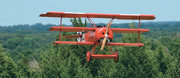
Bill Holland's Fokker Dr. I
Written by Stan Alexander and Bill Holland Insight into building a 1/2 scale model Construction As seen in the October 2017 issue of Model Aviation.
Bonus Photos
Specifications
Wingspan: 142.2 inches Length: 108.7 inches Weight: 122 pounds Engine: 3W 275 Twin Spark Propeller: 37 x 13Equipment Used
Radio: Futaba 12FG transmitter with two receivers, one in the fuselage and one in the top wing; two 4,200 mAh NiMH batteries with BatShare in the fuselage to the receiver and two 2,550 mAh in the top wing; four Futaba S9157 servos, three Futaba S9156s, and a Futaba S3305 for the choke Covering: Poly-Fiber Aircraft Coating and Ceconite 102 Paint: Poly-Tone paint in Tennessee red, white, and blackConstruction
Building that special, once-in-a-lifetime Scale model is the dream of most modelers who try to recreate history with their skills. I’ve been following Bill Holland’s progress for some time now. As he stated, before you start, make sure that your shop, workbench, and transportation can handle a model of this size. This Fokker has its own 18-foot box trailer! Bill’s 21/2-year odyssey included learning new, and sometimes full-scale, building techniques. It will give you a small glimpse into the dedication and determination it takes to see a project such as this to completion. Bill and I hope this article ignites thoughts to help you venture out of your comfort zone and try new techniques—including building a model, no matter what size. The learning process can be frustrating at times, but the result can be rewarding and fulfilling. The project came to fruition during the 2011 World War I Dawn Patrol Rendezvous event in Dayton, Ohio, while chatting with Glenn Torrance. You know how these things go—you talk with other modelers and grand ideas are spurred. Glenn agreed to increase his 33% scale Dr.I plans to 50%, along with a few items, including the wing ribs, cowling, and metal hardware. Glenn’s kits are extremely accurate for obsessive Scale modelers such as Bill. The idea was to have several of these flying at the 2014 Dawn Patrol Rendezvous, kicking off the 100th anniversary of the beginning of WW I. As modelers often do, Bill underestimated what he had bitten off and missed his goal by two years!Airframe
Bill reviewed the plans and realized that there were some major preparations to be done before getting to the first step. The project began with building a workbench to accommodate a roughly 12-foot one-piece wing. So, phase one was joining his two building tables using 8-foot doors. You better have a large shop if you plan to build something of this scale! Additionally, Bill had to decide which types of wood to use and where to order them from. The fuselage was built over the plans with phenolic blocks shaped to receive the rounded dowels. The right and left fuselage sides were joined inverted to ensure that everything was square. Bill found the dowels at Baird Brothers Fine Hardwoods in Ohio. The hardwood used for the front fuselage, gear mounts, and firewall was nine-ply 1/2-inch birch used by cabinetmakers.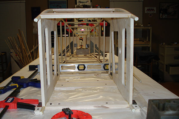
The fuselage takes shape. The carpenters’ level inside of the fuselage ensures that everything is level and balanced.
The full-scale aircraft was steel and had rounded loops at various joints. These added strength and a place to route the multiple internal wire rigging—providing strength and trueness of the fuselage. Bill used a similar approach. He drilled a 1/8-inch hole at a 45° angle and pinned it with carbon-fiber rods. This process worked great and later provided a site at which to add 120 feet of 3/64-inch braided wires and 40 turnbuckles.
Tail Feathers
The tail feathers were straightforward to construct with a few long ribs and dowels. Bill used carbon-fiber rods for the leading edges (LEs) of the horizontal stabilizer and the vertical spar of the rudder. Carbon-fiber rods—both solid and hollow—were used to complete the fuselage, rudder, horizontal stabilizer, elevator, and ailerons. A great source for carbon fiber is a kite company called Goodwinds.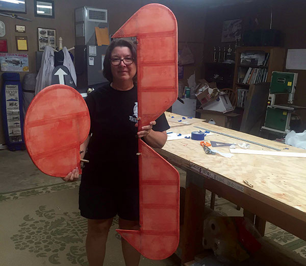
Bill’s wife, Sharon, with the rudder and elevator. This photo provides a good idea of the aircraft’s size.
The horizontal stabilizer was mounted with a three-bolt system similar to the full-scale airplane. The rudder, elevator, and ailerons are attached with scale hinging, which is the same as the full-scale aircraft. Glenn provided the sheet metal for these as he does in the 1/3-scale Fokker Dr.I kit that he offers.
The Landing Gear
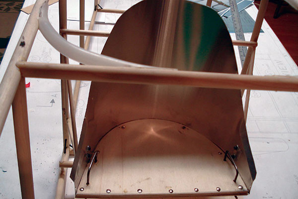
The landing gear involved making a spar box to house ribs that were later sheeted with wood. There are two 1 1/4-inch aluminum tubes in front of and behind the spar box. The center of the spar box allows the axle to move up and down, incorporating a prototypical bungee suspension. Next, the four aircraft-grade aluminum tubing struts were attached to the sub-wing. These were secured to the belly of the fuselage. Bill found the wheels and tires at Tractor Supply Co., all ready to go with bearings installed. These were covered with the same Poly-Fiber as the rest of the model and painted. Bungee cords were wrapped over the axle and standoffs, providing the necessary suspension. The tail skid was made from 1-inch birch and attached to a steel bracket at the base. The top of the skid is internally attached to a bungee, allowing some suspension. The bottom of the skid has a metal bracket with a spade soldered to the center. This provides assistance with maintaining directional control when taking off or landing.Wings
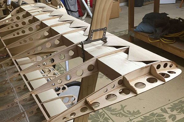
If you like building wings, then this is the airplane for you! The model is built as strong as Anthony Fokker’s original, and the spar box for each wing must be constructed. The top and bottom wings are one piece. The mid-wing is built to incorporate an aluminum spar box to plug into each half. The rectangular aluminum spar box is bolted to the top of the fuselage and is shimmed to establish the wing incidences.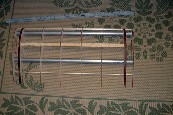
The sub-wing takes shape for the landing gear and the wheels that were purchased from Tractor Supply Co.
The wings on the Dr.I needed to have the correct incidence and be parallel. The center wing cabane mount was made from 4130 chromoly steel. Bill had these pieces welded to match the four 1/4-20 steel bolts on the bottom of the top wing. Next, Bill had to call in the troops to get this right. He needed extra hands! The fuselage, with gear in place, was placed with the tail in flying position. The mid-wing struts set the incidence for both the top and bottom wings. The outboard wing struts had to be spot-on to ensure that the wings were parallel. Additionally, the steel bracket designed to receive the steel pin holds the wing struts in place and had to be right on or the incidence or the parallel measurements would be off. The top wing mounting bracket was secured to the aircraft aluminum airfoiled tubing.
The scale attachment points for the wings and struts..
A piece of steel was welded to the mount shaped like an H. The aluminum tubing was cut at the front trailing edge and the rear tubing LE to receive the piece of steel. This was initially tack welded by a friend who is an excellent welder. Following a check on all measurements and wing incidences, the final welding was done. The next step was securing the steel plates to aluminum struts with steel pins and J-B Weld. This made for a super strong bracket and easy-to-remove top wing. Two flying wires were attached to the steel plate and cross attached to brackets on the firewall. These wires will not have to be taken off to remove the wings for transport.
Cockpit Details
Bill said that the cockpit details and Spandau guns were a lot of fun to build. He likes to doll up any aircraft that he builds. Airplanes that were flown 100 years ago had limited instrumentation; however, the cockpit items available are large and provide the opportunity to build and assemble something special.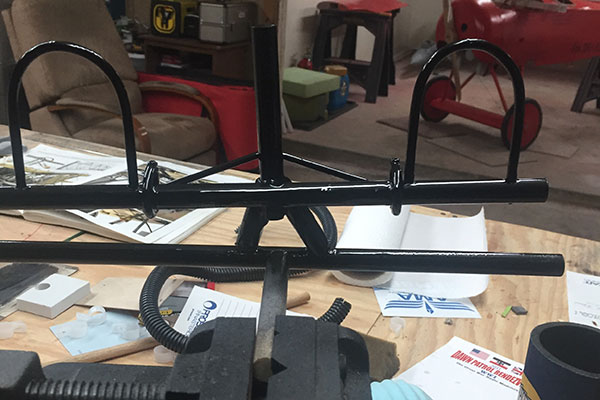
This is the yoke for the cockpit, which was constructed from brass tubing soldered together. The yoke included controls for the guns, the elevator, and ailerons.
The pilot yoke was fairly complex with multiple functions. These included basic throttle control on the left side of the yoke, activation of the guns (either one or both sides together), and elevator-aileron movements.
Spandau Guns
These were started from Balsa USA 1/2-scale kits. There were multiple additions and changes to the final product, but the kit saved Bill a lot of time. Scale modelers find parts in some strange places. Bill created the gun muzzles from cake decorating tips! So look around—you never know where you’ll find parts.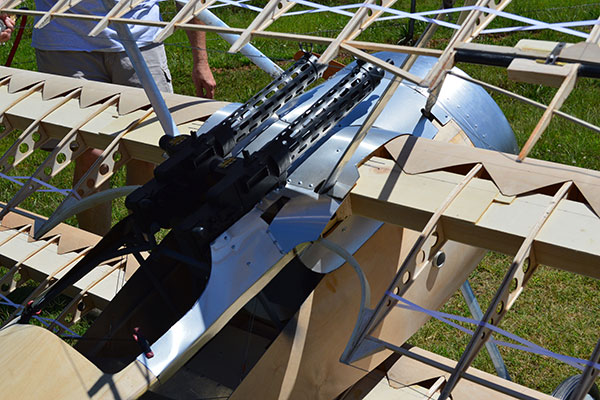
Half-scale Balsa USA Spandau kits were the foundation for the finished machine guns.
The shell retainers on the left side of the guns were added to prevent hot shell casings from falling into the cockpit, which often caused fires or explosions in the full-scale aircraft. These were made from balsa, PVC pipe 90° fittings, and rubber tubing for the scale model. A great friend and fellow modeler, Scott Vickery, provided Bill with the ammunition, which is actual ammo with powder and the firing pin removed.
Additional Cockpit Details
Instruments include mixture control, altimeter, compass, and a castor oil indicator. These were all made by a 3-D printer from IFlyTailies. The Bosch starter magneto switch was made from balsa, plywood, and sheet metal. The seat belts were made from elastic found at a fabric store, with small buckles to tighten the belts. The four straps (two lap and two shoulder) were secured just as in the full-scale aircraft. Bill made each strap bracket from sheet metal.Covering
Bill is an instrument-rated full-scale pilot and long-standing member of the Aircraft Owners and Pilots Association (AOPA), EAA, and AMA. EAA provides many classes across the country to help pilots gain the skills needed to build and maintain aircraft. One of the classes is “How to Cover an Aircraft Using the Poly-Fiber System”. The two-day class is offered across the US, along with classes that include topics such as sheet metal, electrical systems, and working with fiberglass and composites.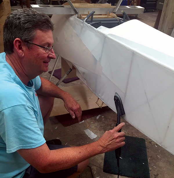
Bill applying Stits fabric covering to the fuselage. A model of this size requires a lot of work to cover.
Bill attended a class taught at an airframe and powerplant mechanics school in Fort Worth, Texas, on March 12-13, 2016. Two club members, Jim and Calvin Ellis, joined him for the weekend class. This outstanding program taught everything from fabric to paint application. The instructor, Lynn Bauer, is just amazing. You’ve likely seen her at Oshkosh AirVenture, Sun ‘n Fun, or in an EAA video. Jim and Bill were miles ahead of the other students having worked with other fabrics on models for many years. Bill used the entire Poly-Fiber system to cover and paint his large Fokker.
The Pilot
This was a finishing touch for this project. Bill researched the physical dimensions of Manfred von Richthofen. Manfred was much smaller than his brother, Lothar. Manfred was 5 feet, 7 inches tall and weighed 147 pounds, according to the reference material found.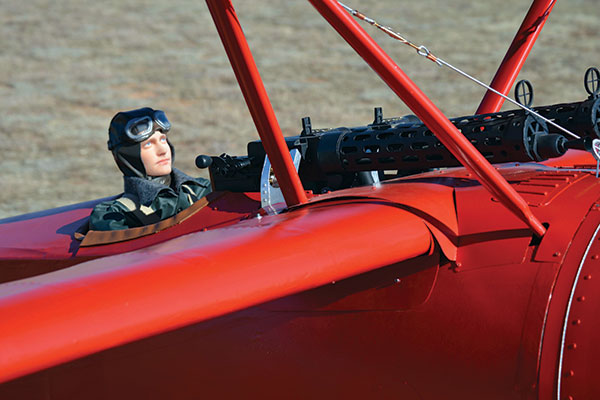
Manfred von Richthofen, the “Red Baron,” is seated in the cockpit.
Bill determined the approximate head circumference and height of the head needed, from the chin to the top. He contacted Lyle Vasser of Best Pilots who makes a 1/4-scale full-body model of Lothar von Richthofen. Lyle offers a variety of pilots and sizes and he agreed to take on this project. Although he’s a master graphic designer and modeler, making a 1/2-scale head was a new venture for Lyle! He used actual photos of Manfred and converted them to a 3-D image with the measurements that Bill provided to obtain the 1/2-scale size. He next manufactured an exact replica of Manfred using a 3-D printer, complete with paint. The final replica of Manfred is an outstanding piece of art!
The pilot’s seat comes together. Bill took classes on metal work through the EAA and used what he learned for some of this construction.
The internal skeleton was made using PVC pipe and light plywood to form a torso. Bill’s wife, Sharon, made the complete body, placed it over the skeleton, and stuffed it with light foam. Sharon also made the pilot’s flying suit, including a flying helmet, from fabric and leather. Manfred’s boots came from a children’s shoe store and are a toddler size 5. The pilot weighs 2 pounds.
Dummy Engine
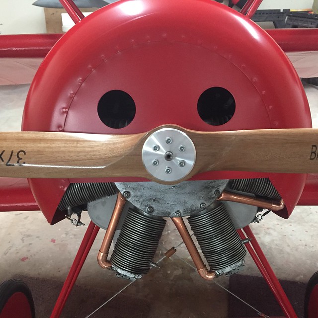
The final piece of this model was the replica rotary engine visible in the lower half of the cowling. The full-scale rotary engine spun on its crankshaft and spinning parts sometimes came off as the airplane flew. The scale rotary engine was made from two fiberglass tubes cut in half. Cooling fins were built from basswood rings and applied to the fiberglass tubes. The crankcase was made from balsa and light plywood. Bill made the simulated valve rockers on top of each cylinder from wood, adding springs and a few screws. The plugs are from Robart Manufacturing air-filling units for retracts and Bill attached a wire—creating a scalelike appearance. The intake tubes were made from copper obtained at a local hardware store.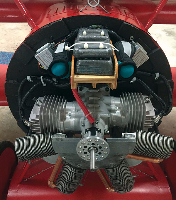
The two-cylinder opposed 3W-275 Twin Spark engine swings a 37 x 13 propeller.
Add a little paint, weathering, and time, and voilà—a dummy rotary engine is born. The dummy engine is attached using three dowels from the firewall.
Color Scheme
The Fokker Dr.I aircraft flown by Manfred featured the original Iron Cross design. In late March 1918, the crosses were changed to the straight Balkenkreuz design. Manfred was killed while flying his Fokker Dr.I on April 21, 1918. Bill’s 1/2-scale Fokker Dr.I features the Iron Cross design.Flying
The big 1/2-scale Fokker Dr.I flew its first flight almost hands off. Living in Oklahoma provided challenging weather at times. Winter and early spring this year were windy and stormy—limiting the right day to maiden the aircraft. This is even more important when it involves test-flying a WW I aircraft. The model was successfully flown at Bill’s local club field in Guthrie, Oklahoma, on April 23, 2017. Bill has since flown it several times. —Bill Holland —Stan Alexander [email protected]Sources:
Baird Brothers Fine Hardwoods (330) 533-3122 www.bairdbrothers.com Ace Hardware www.acehardware.com Glenn Torrance Models (919) 761-1363 www.flygtm.com EAA (800) 564-6322 www.eaa.org ZAP adhesives (863) 607-6611 www.franktiano.com Goodwinds (206) 632-6151 www.goodwinds.com Tractor Supply Co. www.tractorsupply.com Aircraft Spruce & Specialty Co. (877) 477-7823 www.aircraftspruce.com Balsa USA (800) 225-7287 www.balsausa.com IFlyTailies www.iflytailies.com Poly-Tone (800) 362-3490 www.conaircraft.com Best Pilots [email protected] bestpilots.typepad.com F&M Enterprises (817) 279-8045 www.stits.comThis Month's Issue
Join the AMA
![]()


Add new comment