Fighter Face-Off Part Two
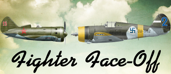
Written by Paul Kohlmann and Derek Micko Scratch-building and flying opposing aircraft Construction As seen in the November 2018 issue of Model Aviation.
Last month, Derek Micko and I introduced our “Fighter Face-Off” joint project. As explained in that article, together we have designed a pair of 60-inch, built-up balsa warbirds representing aircraft that met in combat. Derek went with the Polikarpov I-16 Rata, while I selected the Curtiss P-36/Hawk 75. Free, downloadable plans for these models are available on Model Aviation’s website. Our opening article explained the goals of the Fighter Face-Off that we set for ourselves, and provided background information about the two aircraft that we were modeling. Now that those subjects are out of the way, Derek and I will share our construction experiences in the next installments.
Download free plans

Polikarpov I-16 Rata
Full-size plans Full-size plans sheet 1 (62x27") Full-size plans sheet 2 (67x27") Full-size plans sheet 3 (67x26") Full-size plans sheet 4 (121x26")Tiled plans (8.5x11" pages) Full-size plans sheet 1 (24 pages) Full-size plans sheet 2 (27 pages) Full-size plans sheet 3 (27" pages) Full-size plans sheet 4 (45 pages)

Tiled plans (8.5x11" pages) Full-size plans sheet 1 (12 pages) Full-size plans sheet 2 (12 pages) Full-size plans sheet 3 (12 pages) Full-size plans sheet 4 (12 pages)
Order Plans
Polikarpov I-16 Rata
   |
 |
Curtis P-36/Hawk 75
   |
 |
Curtiss P-36/Hawk 75
Building the Tail Group
Laminated balsa outlines provide strong, lightweight enclosures for the tail group framework. Start by cutting forms for the fin/rudder and the stabilizer/elevator. Foam sheet or plywood works well for the forms. Soften 1/2-inch wide strips of 1/16-inch balsa by soaking them overnight in water. To begin the lamination, wrap one strip around the form, pinning it in place as you go. Pull the strip tightly to avoid kinks in the balsa as it bends around the form. Put a thin, even layer of glue on one side of the next strip and repeat.
The fin and rudder outline is made from three strips of 1/16-inch balsa and a foam form.
Move the pins from the first strip to the second as you go. Repeat for a third strip and set the lamination aside to dry. Carpenter’s glue holds well and can easily be sanded. I like to let the outlines cure for a full 24 hours. After everything has fully cured, pin the outlines down to the plans. Build up the inner framework by assembling the parts in numerical order. Feet on the underside of these parts will hold everything at the right angles. Be careful not to glue the parting lines for the rudder and elevators. They should only be connected by the outlines. Cut through the outlines after the framework is fully assembled to free the parts.

The tail group framework is built within the laminated outlines.
Sheet the upper side of the stabilizer and the fin while they are firmly pinned to the board. This will ensure that these assemblies stay true. After the sheeting cures, unpin these assemblies and remove the feet from the undersides. Now sheet the second sides of the fin and stabilizer.

The completed tail group is shown after sheeting and shaping.
With the tail group construction done, sand the tail group parts to shape by removing the excess material from the outlines. Protect the sheeting and frame parts with masking tape, and sand with 60-grit sandpaper to rough out the shapes. Remove the tape and finish with 220-grit sandpaper. For the prototype, I used Robart 1/8-inch hinge points on all of the control surfaces. I also reproduced the complicated parting line of the full-scale Curtiss as shown on the plans. Curtiss used offset hinges for aerodynamic balancing.

The tail wheel assembly is ready to accept the retract unit from the 55-inch FMS P-40.
This feature isn’t necessary for my model, but it lends to the scalelike appearance. You are welcome to modify the rudder for a straight parting line to simplify the attachment. Simply relocate the hinge axis from where it is shown on the plans to the parting line between V1 and R1.
Building the Fuselage
The upper half of the fuselage is built flat on the building board. Pin the beltline keels K1 over the plans. Preassemble upper former halves F3T through F7T. Install all of the upper formers but F3T and F5T to stand vertically from the board. Use the plans’ paper template to set the angle of F3T and F5T and glue them into place on the keels.
The P-36’s upper fuselage is built on top of the plans.
Tie the formers together with the spine keel K2, the battery tray BATT, and install the servo tray against K1. Next, build the battery hatch opening by gluing lower hatch rails K3 to formers F2T and F3T. Begin the hatch cover by clamping the upper hatch rails K4 to the lower rails. Don’t glue these because they will create the hatch parting line.

The battery hatch is built in place. Note the T-pins that set the gap between the former F3 parts.
Glue hatch formers F1H, F2H, and F3H to the upper rails then tie all of the front formers together with keel K5. Leave a small gap between F3H and F3T to ensure that they don’t get glued together. After adding a few 1/8 x 3/16 stringers to keep the fuselage formers properly spaced, go to work on the Curtiss’ characteristic side windows. Start by tracing the window’s outline from the plans and cut two panels from 1/16 soft balsa. Wet the balsa panels and gently curl them to fit the pockets in formers F5, F6, and F7 and glue them into place. Complete the upper fuselage assembly by adding the rest of the stringers.

The wing saddles have been lightly wetted and curved into place.
Unpin the upper fuselage. Preassemble thick balsa F0 and light plywood F1 to form the firewall. Glue the firewall assembly to keels K1, K3, K4, and K5 and to the BATT tray. Reinforce the wing pin hole in F2B by gluing plywood part WB in place. Create the tail wheel plate by gluing TW, F9B, and F10B together. Build the wing bolt boss by assembling parts WB1, WB2, and F6B. Use epoxy for maximum strength in these critical areas.

The inner panels of the side window are formed from wetted 1/16-inch balsa.
Install all of the lower fuselage formers by gluing them to their upper former mates. As before, all but F3B and F5B will be perpendicular to keels K1. Make all of the lower formers parallel with their upper halves. Tie the formers together with keels K6 and K7. Wet the outsides of the wing saddle parts WS so that they curve as you fit them into place over formers F1 through F6B. Now add the rest of the stringers, working from side to side and checking for twist as you go. Free the battery hatch by cutting through keel K5 and the stringers between formers F1/F1H and F3H/F3T respectively. Lightly sand the fuselage and set it aside for now.
Building the Cowling
The United States Army Air Corps P-36 was powered by the Pratt & Whitney R-1830 engine. Export versions of the Hawk were ordered with either the Pratt & Whitney or the Wright Cyclone. Although the airframes were the same for both configurations, the cowlings were radically different. The Cyclone-powered Hawk had a somewhat cylindrical cowling while the 1830-powered aircraft had better-looking curved sheet metal. The base design here is for the latter, but a builder could easily bash the simpler Cyclone cowling.
After building the left cowling frame on the board, the cowling opening was attached.
Start the cowling by preassembling the thick balsa parts C1 through C4, and then glue the stack together to create the cowling’s opening. Preassemble the cowling formers C5 through C7. Build the first side of the cowling frame over the board by joining the left halves of C5 through C7 to keels C8 through C12 then glue the cowling opening to the front of the assembly. Unpin the assembly and build the right side in the same way but directly on the assembly. After it cures, begin planking from C4 to C7 with 1/16-inch soft balsa. Fill in the area of the gun housings with scrap balsa.

The finished cowling is shown after sanding it to shape.
Sand the cowling to shape with 60-grit sandpaper then finish sanding with 220-grit sandpaper. A mixture of lightweight spackle and Durham’s water putty makes a great, lightweight filler that sands easily. I finished with one layer of 1/2-ounce fiberglass over the whole cowling and a second over the bottom half for the inevitable nose-over.
That’s All (for Now) Folks!
This puts us through most of this project’s woodwork. In the next installment, I’ll knock out the wing and install the internals. After covering, I’ll need to nail down a paint scheme from the huge number of options that the P-36/Hawk 75 series wore. Until then, fly low and build light!
The Curtiss P-36 is fully framed and ready to cover.
Polikarpov I-16 Rata
In this month’s installment, I will discuss the initial construction of the Rata. So clear off the building board, gather some balsa, and let’s get to it!Building the Tail Group
Just as Paul did with the Hawk, I’ll start with the tail surfaces. These also feature laminated edges made from three laminations of 1/16-inch balsa. They were cut using a balsa stripper and one end of them was glued together. These were bent over a form to dry and I glued them together with Elmer’s Glue. In keeping with a traditional build style, I decided to use Titebond wood glue primarily though the build. This really didn’t add much to the build time.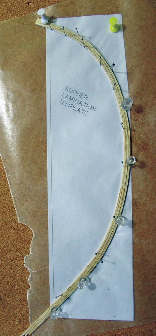
Lamination of three 1/16-inch square balsa around the rudder outline.
Those who are familiar with my Bearcat design will see some similarities. The fuselage is built over the top view of the plans and the formers are split at the horizontal line. The horizontal stabilizer is built first, right over the plans, and remains on it as the fuselage is added around it. The horizontal’s main spars have alignment tabs to account for the taper in thickness.


This shows the horizontal stabilizer and elevator assemblies.
All of the H parts were removed from the balsa “tree” and dry-fitted together. After the alignment was set, I used Titebond to glue the H pieces in place and added some 1/8-inch square and 1/8 x 1/16-inch basswood stringers. The horizontal ribs tab into the trailing edge (TE) and leading edge (LE). Because of the sharp taper, I filled in some of the tab area with scrap balsa for strength.

The formers are painted before the final assembly.
The elevators are built in halves and the ribs key into the LE. Dry-fit all of the parts and trim the TE to the plans and dry-fit it as well. When satisfied with the fit, glue the assembly together. I pinned blocks of 1/4-inch balsa under the TE to eliminate any possibility of warps. I removed the horizontal stabilizer and elevators from the board and sanded them thoroughly. The horizontal stabilizer’s balsa tips were added and the elevator tips were blocked in for strength. The horizontal stabilizer was then pinned back to the board with 1/8-inch balsa shims under H-12 to provide support.

The tail formers and keel are in place.
Building the Fuselage
The full-scale I-16 had a round fuselage. The model’s fuselage is built over the top view of the plans. A 1/4-inch basswood stringer down the center helps with rigidity and alignment. Before pinning it to the board, sand a notch where F-2 would meet the stringer to avoid gluing these two parts together. The half hole in F-2 is for the back of the motor shaft. You will also need to cut a notch in the stringer for WMP-4. Pin the 1/4-inch stringer, WMP-4, and the horizontal stabilizer in place over the plans. Test-fit F-8 to F-10 and V-2 in place over the plans. When I was happy with the alignment, these were glued in place with Titebond. Former F-10 slides between two 1/8-inch stringers on the horizontal stabilizer.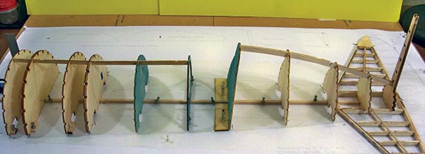
The main formers and keels are in place. Note the temporary mounting tabs on the forward formers.
Because the version I was doing had an open cockpit, I decided to paint some of the parts ahead of time. The full-size interior was a grayish blue and I used rattle-can paint to spray F-5 to F-7 and the instrument panel flat black. Former F-7 and the top keel (K-2) were dry-fitted then glued in place. Former F-4 is a made from F-4 and F-4A glued together. Former F-4A is slightly smaller and this is the break point for the cowl and the rest of the fuselage. Glue the two F-2s together. Dry-fit F-1 through F-6 to the center stringer and add small tabs of scrap balsa to allow for easier pinning.
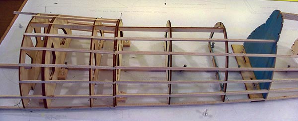

The 3/16-inch square balsa stringers have been added and the vertical stabilizer is complete.
When I was satisfied, I glued these in place along with K-1. This keel part is notched and helps with alignment. The main fuselage stringers are 3/16-inch square balsa cut from medium balsa sheet. The front section near the cowling is not as critical because it will be sheeted with 1/16-inch balsa, but the rear stringers need to be firm to ensure strength. Some of the ones on which I used the balsa got slightly wobbly. Should this ever happen with one of your builds, simply glue another piece to the back of the stringer between the formers. It considerably increases their strength. With the front cowling section finished, the rear stringers were added, starting at the top and alternating sides. The stringers on the turtledeck are 1/8-inch square basswood soaked in ammonia, if needed, so they bend to the shape.

The bottom formers have been added along with the stringers.
The top stringers between F-9 and V-2 were blocked in with scrap to allow for the bottom rib of the vertical stabilizer. The vertical parts interlock and tab into V-2. The top of the fin is a lamination of two 1/8-inch balsa parts. These were rough shaped before being glued to the vertical stabilizer. Scrap 1/8-inch balsa was used to fill in around and in the horizontal stabilizer. The cockpit floor is 1/8-inch balsa cut to fit and painted to match. At this point the model was given a thorough but gentle sanding to blend any rough areas and to prepare it for covering. It was then unpinned from the board. The fuselage was turned upside down and set in a stand. The bottom formers were added and I installed the 1/4-inch balsa center wing saddle piece. Wing mounting plate 3 was added to F-7L and glued in place.
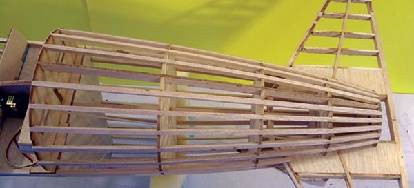
Above and below: The main fuselage assembly is complete and it’s time to set the fuselage aside and start on the wing, which will be covered in the next installment.
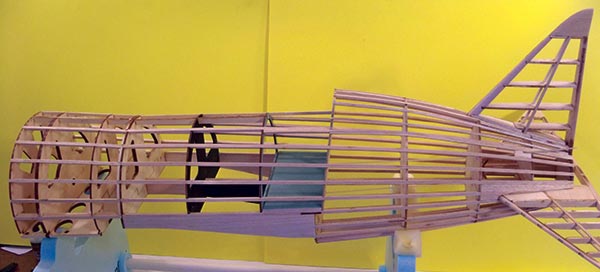
The remaining bottom formers and keel were added next. The elevator servo was mounted under the cockpit and between F-6L and F-7L and the .047 Du-Bro pushrod tubes were added at this time. The bottom 3/16-inch stringers were added and blocked in around the horizontal stabilizer. The battery mounting plate is made from two laminations of 1/8-inch light plywood and locks into the bottom of formers F-1 to F-3. The outer 1/8-inch wing saddles are added between F-4AL and F-7L.

The Rata is shown before covering.
Read more about the construction in the final installment of the Fighter Face-Off series. —Paul Kohlmann [email protected] —Derek Micko [email protected]
Sources:
Model Aviation archives http://library.modelaviation.com Manzano Laser Works [email protected] http://manzanolaser.com



7 comments
Polikarpov I-16 rata
it downloaded OK for me.
Page 4 in Vector Format
plans
good you have the plane of
good day, tell me, trying to
Dimensions of ribs in the sheet 4 vs sheet 1
Add new comment