
Written by Dan Gaston
Go soaring with this training glider
Product Review
As seen in the October 2018 issue of Model Aviation.
Bonus Video
Specifications
Model type: Kit Skill level: Intermediate Wingspan: 35-7/8 inches Length: 19-1/2 inches Wing area: 151 square inches Flying weight: 4.85 ounces Price: $76.98Test-Model Details
Radio: Spektrum DX18; Lemon six-channel receiver; Common Sense RC CSRC35 servos; Castle Creations BEC; receiver battery eliminator used as a voltage regulator; Twisted Hobbies 250 mAh 2S LiPo batteryPluses
• Rolled, full-size plans. • Color manual with sharp, clear pictures. • Layout of all laser-cut sheets for easy parts identification. • Straightforward construction because of great design work. • Great customer support.Minus
• Care must be taken with the fragile components during construction.Image
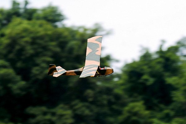
It might not be a graceful-looking sailplane, but the Slingsby is a load of fun in a small package.
Product Review
I have a weak spot for nearly anything of a certain vintage, be it airplanes, cars, or motorcycles. The Retro RC Slingsby T7 Kirby Cadet hit that weak spot dead center. First flown in 1935, the Slingsby was designed as a Royal Air Force training glider and saw service all the way into the 1970s. A scale, vintage glider, the Slingsby kit was designed to meet the Flying Aces Club (FAC) Hi-Start contest rules, but also designed with a conversion to RC in mind. I’ve built many Retro RC kits, and have found them to be well-engineered, great-flying model airplanes. Each of those kits had at least one incredibly clever design element within. The Slingsby kit followed suit with quite a few such solutions to everyday building issues. The kit includes 20 sheets of wood containing 231 laser-cut parts, prebent wire for a tow hook, wing joiners, magnets, rubber bands, an ingenious auto rudder/joystick system, and all of the necessary hardware for the RC version. This kit is not only scale in outline, but it even has scale rib spacing—a lot of ribs in a not-quite-36-inch wing. This should in no way scare anyone with the thought of a complex build because it’s so well engineered that it’s rather straightforward in construction.Image
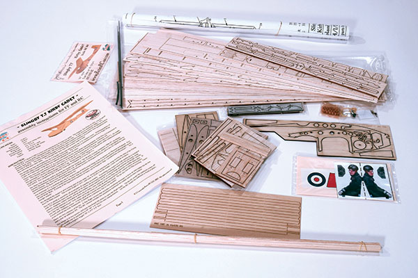
It’s always exciting to open a new kit and look over its contents. The kit itself is quite complete with 20 sheets of wood containing 231 laser-cut parts.
I’ve successfully flown some 2-meter, hi-start-launched sailplanes and enjoyed doing so, so this smaller version isn’t entirely alien to me. With this in mind, I also purchased the Retro RC hi-start and hi-start reel kits. I had my credit card in hand, so I also bought a gaggle of Retro RC’s magnetic building board fixtures, jigs, clamps, and assorted other items to make the building process easier and more accurate.
Construction
Construction begins with the fuselage and, in particular, its plywood keel. Therein lies one of those previously mentioned brilliant design elements. Although not functional in the RC version, the Free Flight (FF) auto rudder system is a treat to behold. The towhook/joystick is a one-piece, prebent wire and is held captive in a plywood lamination that allows it to rock fore and aft.Image
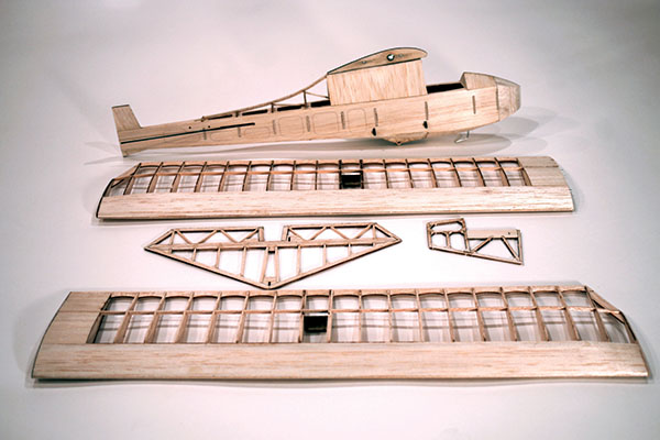
The completed airframe is ready for final sanding and covering.
While under tow, the hook is pulled forward at the bottom, which pivots the joystick to the rear against tension from a small rubber band. When the airplane is released from the tow, the tensioning band pulls the joystick forward releasing the rudder from a straight position to a preset turning position. This is how the glider, in its FF form, is launched straight. When it is released, it is able to glide in circles and stay above, or at least close to, the field. Building the fuselage is a simple procedure, although the structure is anything but simple. There’s a lot going on in the small fuselage, but if the steps in the manual are followed, it’s a breeze. If you are accustomed to building lightweight FF models, the wood used in this kit will be familiar. However, if this is your first attempt at a small, lightweight flier, take it easy when handling the parts.
Image
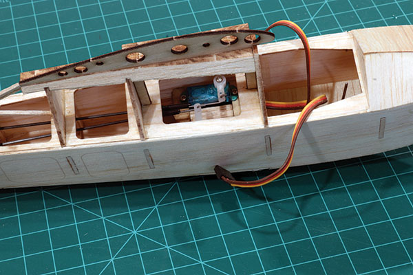
Make sure that everything is in order at this point. As construction progresses, the servos and their linkages become inaccessible.
Throughout the build, options are given to lessen the all-up weight of the model. These are presented early in the preparation of the bulkheads/formers with the choice to remove the core of the formers. The fuselage is built over a flat crutch, first adding the bulkheads then the sheet sides. I found it necessary to lightly swipe some sandpaper through the slots in the fuselage sides to allow the adjoining pieces to easily slide into place. Again, the builder must remember that this airplane is built from thin balsa sheets and if things are forced together, you will hear a horrible cracking sound. A nice surprise was that all of the underside sheeting for the fuselage is laser cut to shape and size making that procedure a snap. The rudder and elevator servos are mounted directly below the fully sheeted wing-mounting pylon. Because of this, they are inaccessible when the fuselage is complete, so it is important to make doubly sure that they function correctly, have a securing screw in the servo arm, and the pushrods are secure. When it is completely assembled, the fuselage is remarkably stout considering how frail the individual components are. One of the final steps in fuselage construction is installing the laser-cut Delrin wing strut anchors. These one-piece, carry-through strut anchors are a nice, strong solution to what would otherwise be a hassle to construct. The fin, which is an integral part of the fuselage, adds yet another nice touch, relieving a builder of the chore of hinge slotting. The fin is made up of a three-layer lamination, the middle of which is relieved for the hinges. When assembled, a perfect hinge pocket is created. The horizontal stabilizer, elevator, and rudder are absolutely straightforward in their construction. These parts are made even easier because every piece that is anything more than a simple bit of strip stock is laser cut to shape. I appreciate the stabilizer and elevators being built as a single unit. The elevator’s hinge line is laser marked rather than cut. When the assembly is complete, the elevators are cut free at the marked line. The rudder utilizes the same lamination method as the fin in creating a perfect hinge pocket. Cutting hinge slots is one of my least favorite building chores, so with the fin/rudder done for me, I chose to sew my elevator hinges. Many might see this as an even more labor-intensive process, but for me, it’s the easiest way to the freest-acting hinge available. As previously mentioned, the wing has scale rib spacing, which means that there are 46 laser-cut ribs. This should not intimidate a builder of any skill level. The accuracy of the laser cutting makes it all fall together in good order. Another of my least favorite building chores is making accurate shear webbing. Thank you Retro RC for providing laser-cut shear webs. The ribs around the lift strut attachment fixtures, and possibly the fixtures themselves, could be somewhat confusing. If a builder reads the written instructions and pays attention to the clear photos in the manual while referencing the plans, it’s plain to see. Concerning the wing strut attachment fixtures, I suggest finish-sanding the bottom of the wing before epoxying them in place. The method used for clamping the upper leading edge (LE) sheeting while the glue sets, and obtaining the necessary washout in the wingtips, is one I’ve never used before. Sections of 1-inch aluminum angle are used to trap the LEs and trailing edges (TEs). The two aluminum angles are simply rubber banded together, pinching the wing chordwise and applying even pressure all along the upper LE sheeting. The tip end of the TE aluminum angle is blocked up while the glue sets to lock in the washout. All that remains for wing construction is to install the wing joiner tubes in the laser-cut holes followed by sheeting the center section. Now the entire airframe can be given a final sanding in preparation for covering. With the exception of the spine, I chose to cover the fuselage and tail surfaces with Japanese tissue. For the spine, I used Polyspan adhered at the edges with SIG-MENT adhesive. Polyspan has an amazing ability to follow compound curves, shrink wrinkle free, and make it appear as though I know what I’m doing! The tissue was applied with Sig clear butyrate dope thinned 50/50, and sealed with two brushed coats of the same. The wings were covered with Polyspan adhered with Deluxe Products Cover Grip. Be sure to run the Polyspan’s grain in the spanwise direction. The wing also received two coats of thinned dope. After this step, the finishing process took a turn for the worse. There were no problems encountered with any of the products used—just the manner in which they were incorrectly applied. An airbrush is a wonderful tool when used correctly. Unfortunately, I’ve yet to learn how to use one in such a manner. My paint of choice was Tamiya acrylic thinned with alcohol. This fantastic paint is available in more colors than I ever knew existed and it cleans up with water. I chose a brown/green camouflage scheme for the upper surfaces, with, yellow on the underside. My ineptitude with the airbrush left me with a model that should only be viewed through welding goggles, but if we don’t try these things, we’ll never acquire new skills. After the flying portion of this review is completed, the airplane will be stripped and re-covered.
Image
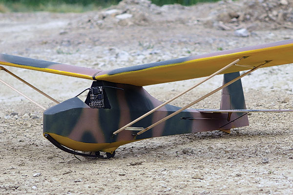
The Slingsby is at rest before its maiden flight. The exposed receiver will be tucked away after everything is sorted out.
Flying
The lightweight hi-start from Retro RC was set up per FAC rules (found on the company’s website) in case I decided to try my hand at FF gliders. After a couple of test glides to verify that all was well, the hi-start stake was driven in at the far corner and the rubber portion secured to the stake. This is where I made my first mistake of only slightly stretching the rubber to perhaps twice its natural length. My reasoning was that I only wanted a gentle launch at first. After the Slingsby left my hand, the energy in the rubber was almost immediately spent. The glider lost all forward momentum, stalled wildly while still on the hook, and slammed to the ground on the gravel access road. As previously mentioned, this airplane is built to last because this body slam into the gravel caused absolutely no damage. Right back on the hook it went, with the rubber stretched to maybe four times its natural length. This time the Slingsby flew straight as an arrow in a 30° to 40° climb with no input from me. At the point where the rubber has expended all of its energy, everything came to a standstill and another tip-stall ensued. Some scary moments followed because I could not get the airplane to disengage from the tow ring, but this time I had some altitude with which to play. After it was off the hook, the glider settled into a slow, gentle glide, allowing me to breathe again and eventually landing right on the runway. After a few more attempts with only slightly better results, I decided to pack it in for the day and give some thought to what I might be doing wrong. In the end, I took the easy way out and called Mark Freeland of Retro RC to pick his brain about my less-than-stellar results. Mark asked me a few questions and the solutions were instantly apparent to him. First and foremost, I flew on a calm day, which is far from ideal. Flying into a slight breeze helps get the airplane aloft and has it dropping off the hook at a higher altitude. Opening up the angle of the hook just slightly cured that scary tow ring hangup, resulting in a far more enjoyable flight. I was also instructed to stretch the rubber to at least five or six times its natural length. Armed with these few tips, my subsequent flights have been a joy. I’ve yet to find a thermal, or make the hunt for that thermal look graceful, but the challenge is where the fun is for me. The Slingsby T.7 Kirby Cadet from Retro RC is yet another winner in the company’s ever-growing lineup of well-engineered kits.Image
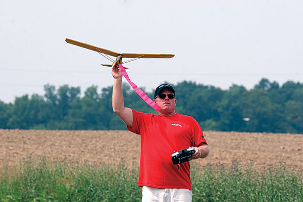
The author is attempting to look confident before the first hi-start launch.
—Dan Gaston [email protected]


Comments
Add new comment