
Written by Curtis Mattikow
This easy method allows you to propel almost any model
How-to
As seen in the May 2009 issue of Model Aviation.
With the inexpensive and powerful outrunner motors and Li-Poly batteries that are available nowadays, a new wave of larger models is being converted from glow to electric operation. All of these bigger aircraft come with beam mounts that are unsuitable for motors, and motors are usually considerably shorter than their glow-engine equivalents, so the motors can seldom be bolted directly to the firewall.
A few large motor mounts are available commercially, but they are sometimes expensive and hard to get. This photo-illustrated article will show you the simple steps required to mount motors. The only things necessary are a few dollars’ worth of plywood, which you might already have in your scrap box, and maybe an hour’s worth of time.
What You Need: A table saw with a fence is handy for accurately cutting the plywood. That’s a long, blister-producing job with a hand saw.
Make sure you have a ruler, a pencil, five-minute epoxy, screws for mounting the motor, and the appropriate plywood. I used 1/4-inch aircraft grade, which you can obtain from Midwest Products. The motor is a Tower Pro from Nitro Model Planes that is equivalent to a .50-size glow engine.
You could go down a size in plywood to 3/16 for smaller motors, but chances are that 1/4 will be more than adequate for even the largest motors—up to the 90 class. Lightening holes saved close to 1/2 ounce on this mount without sacrificing rigidity. Plus, they look cool.
Mounting Tips: Check out the step-by-step photos for the lesson. Notice especially how your propeller driver/spinner/propeller combination go together; some electric propellers extend rearward behind the propeller driver, as do some spinners, so account for those items when taking measurements.
I highly recommend that you firmly clamp the assembly while it cures; clamping pressure makes a huge difference in an epoxy joint’s strength. A roughing option is to drill a few 1/16-inch holes in the gluing areas, to give the epoxy more bite.
This is a quick technique that costs you almost nothing, and the results are extremely strong and rigid. It took me less than an hour to make both mounts for the Nitro Model Planes B-25 Mitchell. I spent more time shopping unsuccessfully for appropriate mounts at the hobby store and on the Internet than it took me to make this modification.
Give it a whirl!

Measure the amount that the cowl will overhang the fuselage. In this case, it’s 1cm. Make a note of that figure.
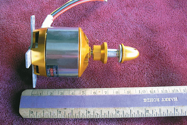
Measure the length of the motor, from the metal cross mount to the portion you want sticking out of the cowl. Write that down. As shown, it’s 6cm. Check to see how your propeller driver, spinner, and propeller combination go together.

Measure the cowl from front to back, which is 12.5cm here. Add the overhang, the motor length, and the thickness of the plywood (.5cm is roughly equal to 1/4 plywood). That is 1 + 6 + .5 = 7.5cm.

Subtract 7.5cm from the cowl length, which is 12.5 - 7.5 = 5cm. That’s the depth of the mount you will make. Draw a line across your plywood at that dimension.

Measure the width of the cross mount; the one shown is 5.5cm. Draw four vertical lines across the plywood, 5.5cm apart. Be sure to account for the material that may be removed by your saw blade, too.

Cut across the lines you made, to make four identical pieces. If you like, you can stack the pieces and drill lightening holes. Keep the holes at least 1/4 inch away from any edges.

Epoxy and clamp the four sides, overlapping them as shown. Place the assembly on plywood and trace around it. Cut out the marked piece; that will be the firewall.

Draw diagonal lines across the firewall to establish the center. Drill a hole, as required, to clear the rear of the motor shaft and the shaft retainer. Epoxy the firewall to the motor mount.

Measure and mark the horizontal and vertical centerlines of your firewall, as well as the halfway points of each side of the mount. Tape the mount to the firewall, aligning the marks on the mount with the lines on the firewall.

Trace around the mount onto the firewall, and remove the mount. Rough up the areas marked on the firewall; epoxy adheres better to an uneven surface. Drill a hole above or to the side of your mounting area, for your wiring to go through back into the fuselage.

Use plenty of epoxy to install the motor mount to the firewall. Stand the fuselage on its tail and weight it down, to provide pressure as the epoxy cures. I painted the mount and firewall so that it would look better through the open radial cowl when finished.

Mark and drill pilot holes, and install your motor on the mount using screws. Back the screws out, remove the motor, and harden the screw holes with thin cyanoacrylate. Let that dry, and then reinstall the motor and screws for maximum security.

The great thing about motors is that there is no needle valve or exhaust muffler to carve out of the cowling. Ensure that there are openings through which cooling air can pass.
-Curtis Mattikow [email protected]


Comments
motor mounting
I prefer to add T nuts behind the firewall to capture the motor mounting bolts.
Large Brushless Motor Mounting Article
How-to article is good but I would recommend adding blind or T-nuts and using allen head bolts instead of wood screws for large motor safety. Before epoxying mount box to the firewall install blind nuts inside the mounting box. Drilled holes should fit the shank of the blind nuts closely. Coat allen bolts sparingly with Vaseline. Apply epoxy to the area around the hole inside the mount. Draw the blind nuts into the ply by tightening bolts, then coat the outside of the blind nuts with epoxy with bolts in place. LET EPOXY HARDEN COMPLETELY. Remove bolts and mount motor. Adjust down and right thrust angles with washers as desired. It helps to CYA washers together to help install them with minimum hassle. Have somebody hold model vertically to help adding washers. Another tip, use non-hardening (blue) thread locker on all brushless motor X-mount screws, bolt on prop adapters and set screws. I lost a motor when four tiny screws came undone.
Great 'how to' article.
Great 'how to' article.
The slower the epoxy cures
The slower the epoxy cures the better the holding strength. With the newest classes of outrunner motors, and the torque that they produce I would be inclined to use the slowest setting formula available for larger size motors. Triangle stock at the firewall joint would also be a good idea also, greatly increasing the holding strength again. If substituting a motor for a glow engine the weight is not an issue, but the rigidity of the mount is. Experience tells me that everything on an airplane is crucial and skimping on flight critical components gets expensive fast.
great article
loved this article! I am in the middle of a big gas conversion and this answered a lot of questions!
strength of motor mounts
if triangle pieces of hardwood was placed in the inside corners of the mounts,epoxyed in place would greatly increase the stifness of mount.small weight increase. about 1/4 inch would be enough.
Add new comment