


Build the Sky Zoomer

Designer builds his dream powered glider
DOWNLOAD FREE PLANS HERE!
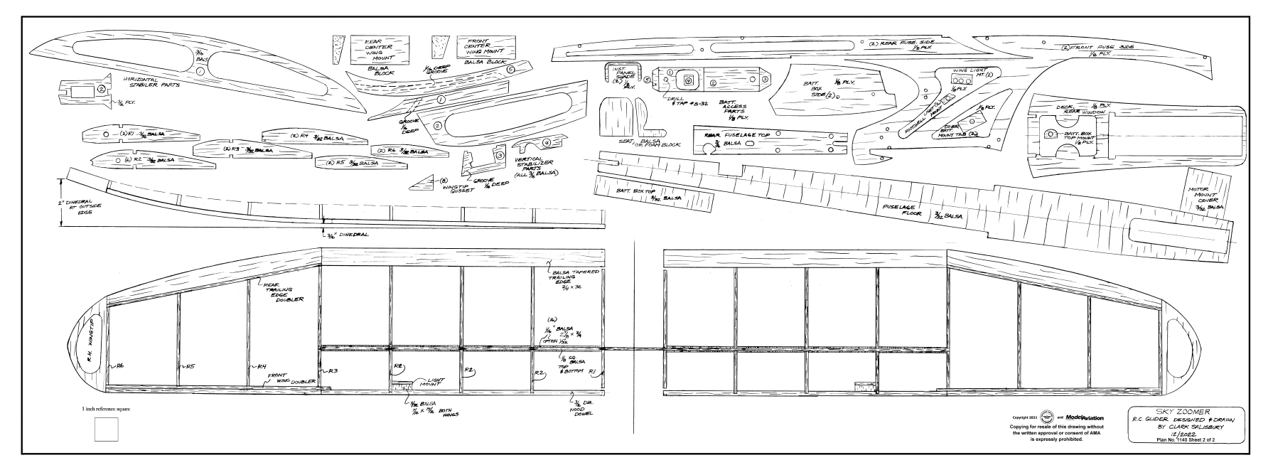
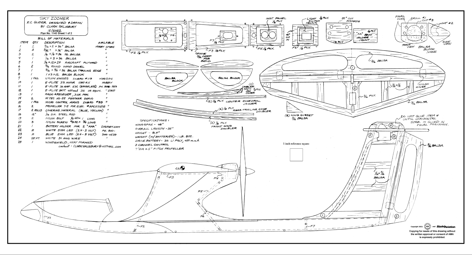
PURCHASE SKY ZOOMER PLANS HERE:
plans.modelaircraft.org/product/sky-zoomer
Tiled Versions
Full Versions
Before we start building this RC-powered glider, I need to explain why I even wanted to design an airplane such as this. Basically, it’s because I love flying my UMX Radian. The really neat thing about a powered glider is that you can fly it during any season of the year. Because it is handlaunched, a runway is not needed, and for landing, either grass or snow works just great. It also has no landing gear, so it can just land on its belly.
So far, this winter in northern Utah has been the coldest, with the most snow we have seen in many years. I thought in this bleak winter, why not design an airplane like the Radian, except as a pusher design because front-mounted folding propellers with small motors are not available.
So, it was to the drawing board for me. One feature that is essential for me is having lights on an airplane. In the winter, we have more night than day, so flying at dusk or at sunrise is really fun if the model has lights. Therefore, the Sky Zoomer has lots of lights, which are especially visible when the airplane is coming toward you.
Another important factor in the design is being able to fit the airplane in a car without removing its wing, so 48 inches is my wingspan limit. I also just love the look of a full-scale airplane with real windows and a scale pilot inside looking at gauges.
Let’s get right into building.
At a Glance
Specifications
Wingspan: 48 inches
Length: 35 inches
Weight: 1 pound, 8 ounces with battery
Test-Model Details
Motor used: E-flite 370,1,080 Kv or equivalent
ESC: E-flite 30-amp
Battery: 3S LiPo 450 mAh
Servos: Two Hitec HS-55
Propeller: 7 × 5 electric
Purchasing the Wood
When buying wood at your local hobby store, make sure that it is not warped or bowed. This is especially important when buying the 3/16-inch dowels. They become the wing’s leading edge (LE) and must be straight. Any balsa sheets should be straight and roughly the same density if you are buying more than one piece.
Cutting Out the Parts
Figure 1
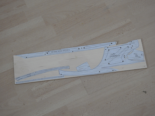
As shown in Figure 1, I have laid out all of the 1/8-inch plywood parts that need to be doubled on a 6 × 24 piece of plywood. That is done by cutting your 12 × 24 piece exactly in half the long way. You’ll notice that there is quite a bit of plywood left over in the middle; that will be used later when cutting out the formers and other parts where only one part is needed.
Figure 2
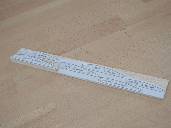
When cutting out the wing ribs, as shown in Figure 2, you will notice that there are many that are doubled, or, in the case of R3, six are needed, so stack the 3/32-inch balsa as thick as needed to cut out all of each rib type at the same time.
Vertical and Horizontal Stabilizer
Figure 3
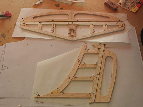
In Figure 3, the stabilizers are shown pinned to my building board (which is a piece of drywall). Remove them and sand the edges to a nice radius. Notice that space has been allowed in the vertical stabilizer for the servo mounting.
The horizontal stabilizer has a rectangular hole in the center for the servo. You will need to make a groove in the front of the vertical stabilizer for the servo wires to go down to the hold in the top of the fuselage. At this point, it would also be great to make the slits and test-mount the five nylon hinges for the control surfaces. They will be epoxied in later.
Figure 4
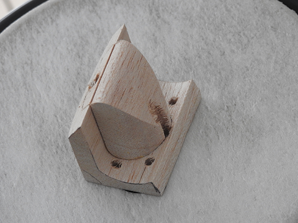
In Figure 4, start with the nose of the fuselage. Drill and cut it out according to the notes on the plans. It is important to note that the center of the nose is cut out because I have designed a bit of a shock absorber into the design so that the center can be pushed in to absorb some of the energy in case of a front impact.
Figure 5
Figure 5 shows the nose piece center being cut 1/4 inch. This space will be replaced with shock-absorbing foam later.
Figure 6
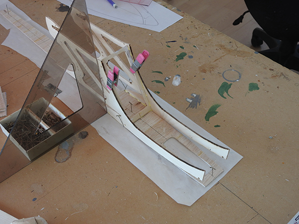
Figure 6 shows the fuselage sides being glued to part of the floorboard. The F2 former is glued in place using the tabs and holes. Make sure to use a square as shown so that the sides are perpendicular to the floorboard. Only apply glue from the notched part of the floorboard up to F2. I drew a 28-inch long black line on my drawing board. This is a good way to keep the center of the fuselage straight because you can keep the floorboard centered on the line as you build.
Figure 7
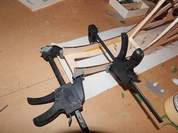
Figure 7 shows the front of the floorboard being glued to the front of the fuselage sides. The front of the floorboard should be flush with the front of F1, and the clamps should be at least the width of the fuselage.
Figure 8
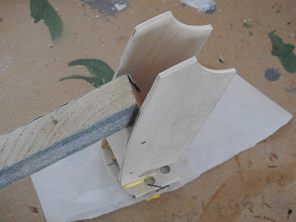
Figure 8 shows the battery box sides being glued to F1. The top of the battery box sides should be flush with the top of F1. Before doing this, however, the battery box sides should be held the proper distance apart by tack-gluing the AA battery mount inside. It will be removed later when you are wiring the lights.
Figure 9
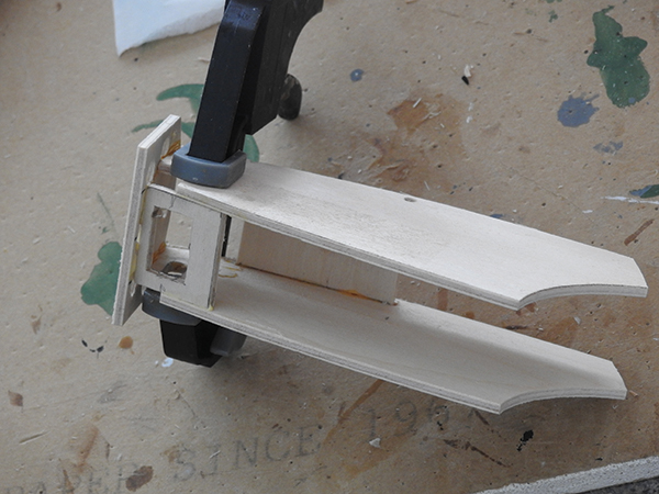
Figure 9 shows the light-switch mount being glued to F1 and to the bottom of the battery box sides. It should be flush with the bottom of those sides.
Figure 10
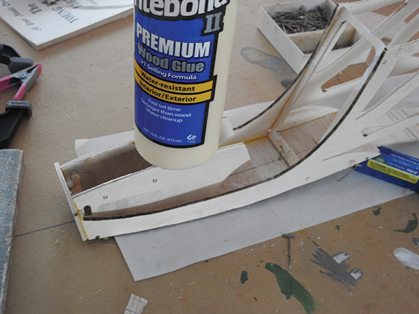
Figure 10 shows the battery box, with F1 being glued to the floorboard. I used a weight to make sure it stayed in position during drying.
Figure 11
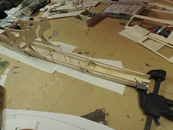
Figure 11 shows the rear fuselage sides being glued to the rear floorboard. Again, make sure the centerline matches up as you glue this. Also note that the rear floorboard slants upward for the last 4 inches.
Figure 12
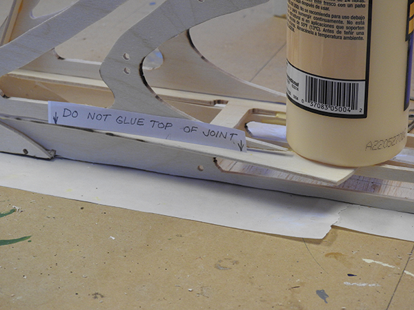
Figure 12 shows the rear window deck being glued in position. Glue to the bottom rear fuselage only. The upper part of the fuselage will later be bent over closer to the centerline.
Figure 13
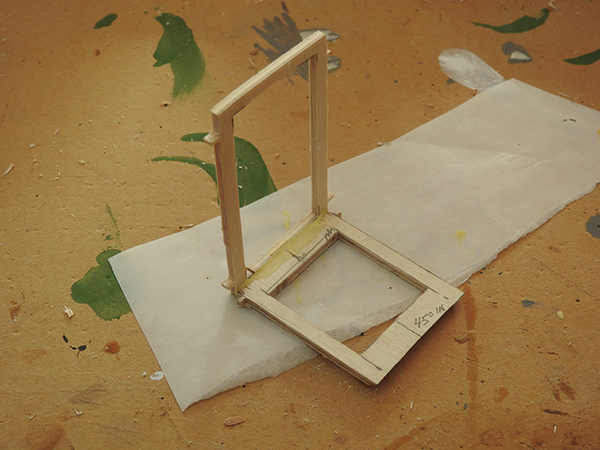
Figure 13 shows F5 and F6 being glued together. This considerably simplifies the next step. Test with the holes and tabs in the fuselage side to get the angle correct.
Figure 14
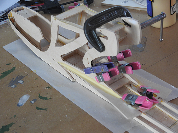
Figure 14 shows the F5 and F6 formers, as well as the F4 motor mount being glued into the upper fuselage sides, held together with clamps. It is fine to glue the rear window’s upper side to the fuselage sides.
Figure 15
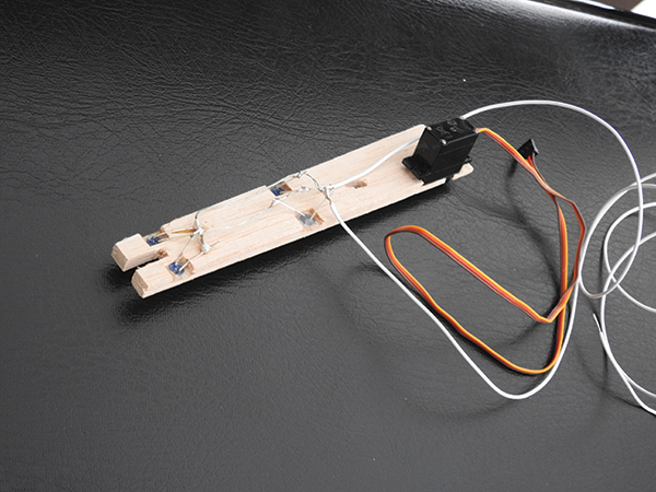
Figure 15 shows the underside of the rear fuselage top. Four blue LEDs are epoxied into the 3/16-inch diameter holes. Every LED has a short and a long connection tab on it. The short connection to your battery is positive, and the long is to the negative side of the battery. The LEDs will only work if you wire them this way. They do not work when wired backward.
Figure 16
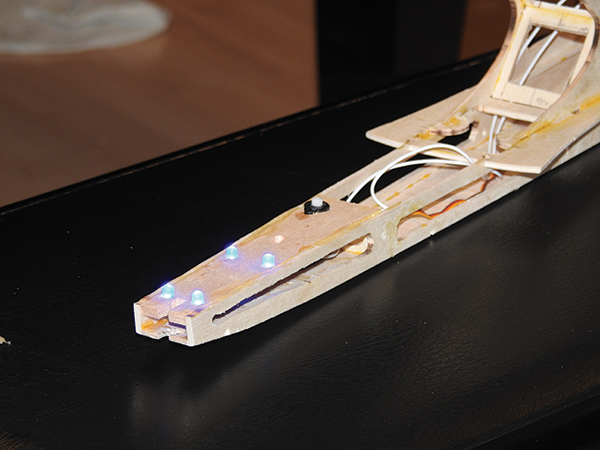
Figure 16 shows the top side with the LEDs wired to the AA battery holder. Test every LED before you go through the trouble of soldering. I found out that I had one LED that was no good and I threw it away. I had to unsolder one because I did not test it first.
Figure 17
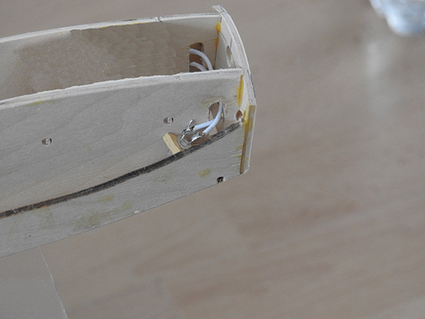
Figure 17 shows the white footwell LED soldered in position. This is located up front on the side of the battery box, and there is one on each side.
Figure 18
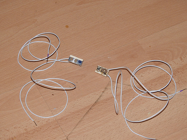
Figure 18 shows the wing lights in the light mount. They are soldered and have been tested for use later on both sides of the wing. I used one blue and two white lights on each side.
Figure 19
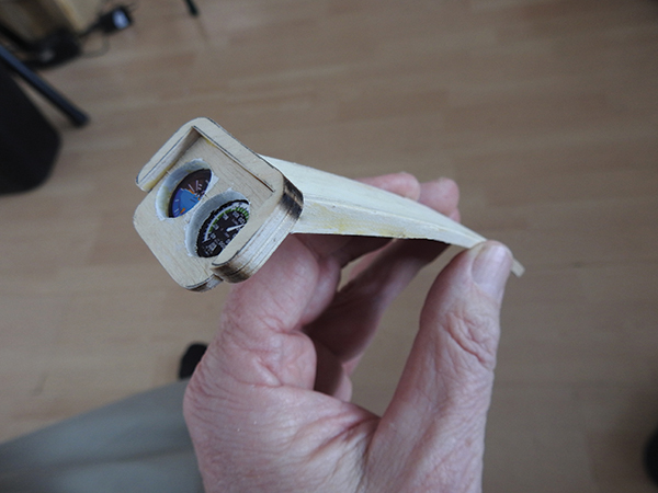
Figure 19 shows the instrument panel, the gauges, the instrument panel shade, the battery box top, and the battery box top doublers all glued together. Check the angle at which the instrument panel glues to the battery box top by laying these parts on top of the battery box sides.
Figure 20
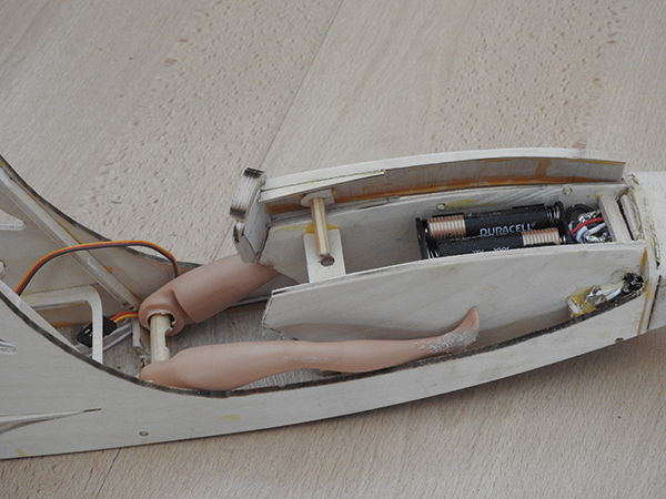
Figure 20 shows the bottom side of the battery box top, with the mount piece glued to it. Cut a 1/2-inch piece of the 3/16 wood dowel and insert that into the mount piece. Between the battery box sides is the mount tab, which has a 3/16-inch diameter hole in it so that the battery box top can be held in place with friction.
Figure 21
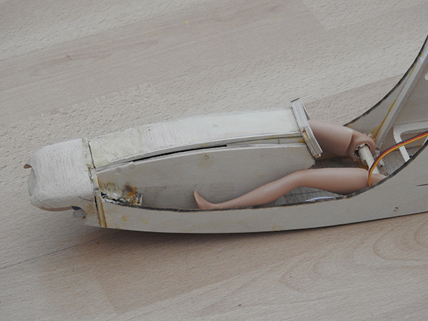
Glue this in first then glue the dowel into the mount piece. Hold the correct position by holding the assembly built in Figure 19 to the battery box sides. Note that there should be a tapered gap between the battery sides and the top, as shown in Figure 21. This is intentional for styling. I have started to modify the pilot’s legs, as you can see in Figures 20 and 21. She will be sitting directly on the battery-to-ESC wires later, so she has a wooden dowel hip joint. Figure 20 shows the AA batteries in place that are used for the LED lighting. When I finished the model, I discovered that, in order to get the center of gravity (CG) right, I had to move the AA batteries rearward. The best place to mount them would be behind the pilot, with access from the bottom of the fuselage.
Figure 22
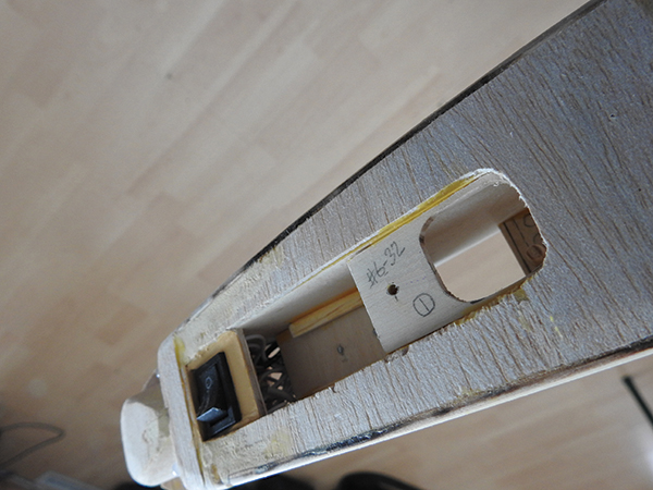
Figure 22 shows the front bottom of the fuselage. Item 1 of the drive battery access parts has been glued to the top side of the floorboard. The square hole should be flush with the hole cut out in the floorboard.
Figure 23
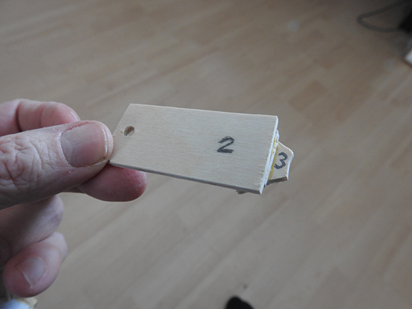
Figure 23 shows the remaining battery access parts glued together. It is hard to see it, but between item 2 and item 3, item 5 is sandwiched in the middle. It is important to allow access to the door assembly to allow correct alignment.
Figure 24
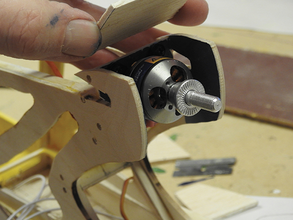
Figure 24 shows the motor mounted and the cavity painted blue. The four screws—especially the upper ones—are nearly impossible to screw into place after the top piece has been glued on. In my fingers, I am holding that top piece, which was glued next. This completes the fuselage. It’s not shown, but I painted the inside of the cockpit yellow. I also painted the area blue around the light switch on the bottom.
Building the Wing
Figure 25
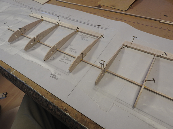
Figure 25 shows the plans laid out on the building table, with a sheet of waxed paper covering it. First, lay down the 1/8 × 1/8-inch square balsa strip and pin it to the table. It goes from R3 to R3 on both sides of the wing. Make sure you do this as one continuous strip, not cutting it at the wing center.
Now pin down the 3/4-inch trailing edge (TE) to the plans, as shown, from R1 to R3. This will be done in two strips, one for the right wing half and one for the left wing half. Glue all of the R2 ribs to the TE and the square strip that was pinned down earlier. Glue the R1 rib to the square strip as shown. Note that it does not touch the TE. This is for the dihedral joiner that will be put in later. Let this assembly dry.
Figure 26
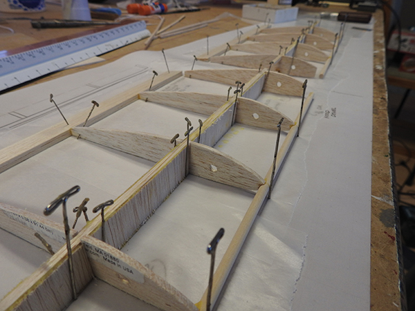
Figure 26 shows the wing’s LE, which is the 3/16 -inch dowel that is glued to the front of the R2 ribs. Note that the LE is elevated roughly 3/32 inch above your building board. It should be cut to length, as shown on the plans.
Glue in the top part of the wing spar, which is a 1/8 × 1/8-inch balsa strip. This should be cut at the middle of the wing so that there is a 1/16-inch gap right in the center of the wing. Glue on all of the webbing that will finish the wing spar on both sides. This is 1/16- or 1/32-inch (optional) thick balsa and there will be 16 pieces glued, which are 2-7/8 × 3/4-inch balsa pieces. Do not glue the web pieces in the center between the wing halves at this time.
Figure 27
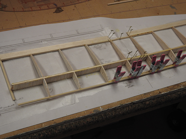
Figure 27 shows the dihedral joiners added at both the front and rear center sections of the wing. The 1/16-inch balsa webbing has been glued to the spar on both front and rear of the square balsa strips. The correct dihedral is held by laying a 3/16-inch dowel under the wing at the R3 location on both wing halves.
Figure 28
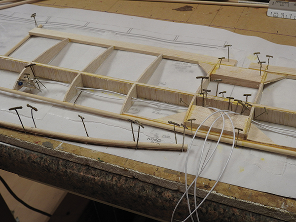
Figure 28 has a lot going on. In the front of the photo, you can see what will be the LE of the curved part of the outside of the wing. The 3/16-inch dowel has quite a lot of curvature. I submerged a dowel in water for approximately 4 hours so that it would be soft enough to bend.
I laid the wet dowel on top of the 1/8-inch plywood front wing doubler and pinned it to force it into the correct curvature, letting it dry overnight. I then glued it to the 1/8-inch front wing doubler. It was pinned again to hold the curve.
Follow this same procedure for the TE, again first soaking the balsa for 4 hours. Make sure that you make right and left parts when doing this. I have also installed the LED lights that were soldered together and mounted on the 1/8-inch plywood piece. Install them in the location on the drawing and make sure that the light mount is flush with the top of the wing rib. At the wing’s center, the balsa block front and rear wing mounts are glued in place and four of the 3/16-inch wing gussets are added.
Figure 29
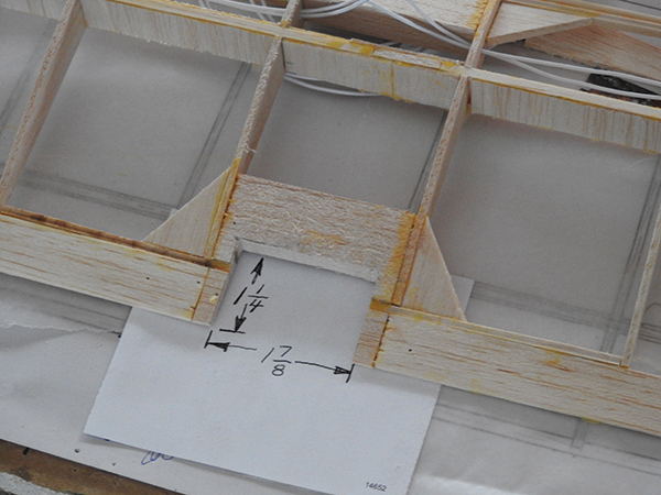
Figure 29 shows that the center rear portion of the wing has been cut out. Cut it as shown at 1-1/4-inch deep and 1-7/8-inch wide. Make sure this cutout is exactly centered.
Figure 30
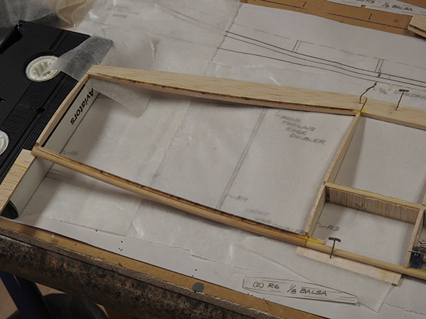
Figure 30 shows an old VHS tape laying over the plans on top of the R6 rib. A VHS tape is exactly 1 inch wide, so if you don’t have one, use a block that is straight and 1 inch thick. The curved LE you made earlier is laid flush with the 1-inch spacer but with a 3/32-inch spacer under it. Where the curved LE meets R3, there should also be a 3/32-inch spacer under it. On the backside, the curved TE should be laid against the LE at R3. R3 is glued in at the same time as R6, which connects the front and rear curved edges.
Figure 31
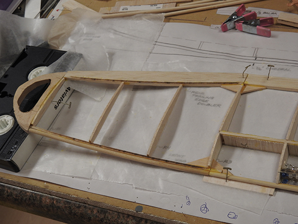
Figure 31 shows the remaining pieces of the wing being added. Let this assembly dry completely. Unpin the wing and repeat the last two steps for the other side of the wing.
Final Assembly and Covering
Figure 32
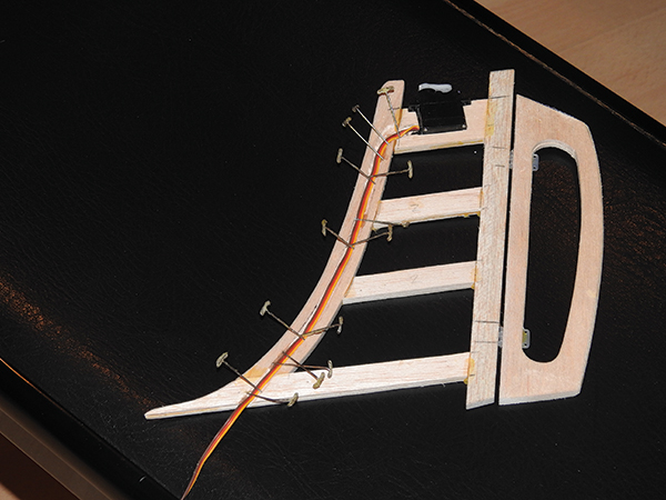
Figure 32 shows the vertical stabilizer with the elevator servo epoxied in position. The front of the stabilizer has been grooved out to a 1/16-inch depth so that the servo wires can be buried and not seen. These wires should be epoxied into the bottom of the groove. I used a lot of pins to hold the wires down as the epoxy dried.
Figure 33
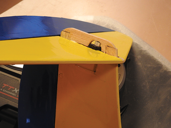
Figure 33 shows the vertical stabilizer covered with the blue and yellow material that I used. The horizontal stabilizer has also been glued into position for the T-tail configuration. Item 4 of the vertical stabilizer parts can now be glued in position. This piece keeps the horizontal stabilizer from coming off in high-G maneuvers. Item 4 can now be covered with the covering material. I added covering material pieces to all of the connection inside corners on the entire tail assembly to take the load again during high-G maneuvers so that the glue alone doesn’t hold the tail together.
Figure 34
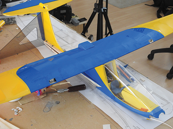
Figure 34 shows the windshield in position. Use two #8-32 screws at the bottom of the windshield to hold it in place. The battery access cover under the fuselage should be held in place with a #8-32 nylon screw. After the wing position is established, drill through the front of the wing in two places and drill and tap the fuselage top to a 1/4-20 thread so that the two 1/4-20 nylon screws can hold down the front of the wing.
The rear of the wing is held in position by the front of the motor mount. The last steps are to check that both wing halves are the same with no warpage. Make sure the motor is turning the correct direction for forward thrust. Note also that the numbers on the front of the propeller should be facing forward. The propeller is an airfoil and produces a lot more thrust if the curved part of the blade is forward.
Make sure the radio sticks are oriented correctly so that the rudder and elevator go in the correct direction. If they’re not, use the reversing switches on your radio to correct it. You should be seeing approximately 15°of movement on both the rudder and the elevator.
Flying

I recommend that flying this airplane is a two-person operation—at least while launching. The launcher should run into the wind and hold the model slightly in front of the CG. Launching can be level or slightly upward, and the pilot should be prepared to adjust as required during the climbout. This airplane is a glider, so it is fun to attain as much altitude as you can while still keeping it clearly in view, and then just have fun gliding downward. If there is a little wind, the model will basically remain still in the air, as long as the nose is pointed into the wind.
Of course, going the opposite direction, the model becomes fast quite quickly. You won’t want to go far before turning back into the wind. Landing can be done deadstick and into the wind.
Every time I tested the prototype, it was during windy conditions, but I think this airplane would fly smoothly in calm conditions. You can watch the first flight by going to my YouTube channel.
Have fun with this airplane. I did.
SOURCES:
Clark Salisbury’s YouTube Channel
This Month's Issue

Join the AMA
![]()


10 comments
Hi, 1140 Sky Zoomer full plan
Thank you for informing us
Sky Zoomer Assembly
1140_Sky_Zoomer plans
Thank you for informing us
1140 Sky Zoomer full plan
Thank you for informing us
Sky Zoomer plans downloads
download plans for Skyzoomer
Canopy
Add new comment