Written by David Buxton
As seen through the eye of a current probe
Technical
As seen in the May 2017 issue of Model Aviation.
Understanding how digital servos work as a switched mode power device will help you to make better use of them and gain a better understanding of their power supply requirements. We will start by taking a look at digital servos as seen through the “eye” of a high-performance current probe. With these insights, we can then discuss power supply solutions that will enhance servo performance and keep your radio properly supplied.
Switched Mode Power
Digital servos use pulse width and pulse rate modulation to power the servo motor. The servo can be pulsed in the forward or reverse direction. The four solid-state switches, under the control of the servo’s micro controller, are either open circuit or closed circuit for ohms law efficiency.
Switched mode servo motor control system.
Through the Eye of a Current Probe
The experiments that I conducted used an Airtronics 94780 coreless digital servo, a 5-volt direct-current (DC) power supply, a Tektronix TCP0030 current probe, and a Tektronix DPO7354 digitizing oscilloscope. The waveforms that follow were retrieved from the oscilloscope.
High-performance Tektronix TCP0030 current probe.
For the “holding position against high torque” waveform diagram, I applied an aggressive amount of torque with my fingers. The servo was making enough noise to convince me that it was under duress and it was aggressively holding position.
The average current was 0.3 amps, which is what a digital multimeter (DMM) would read. Peak pulsed current was 5 amps. We can calculate that the servo’s resistance at zero rpm is 1 ohm, while a pulse is an active and open circuit between pulses.
Holding position against high torque.
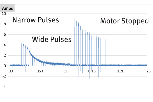
Under much lighter loads, the pulses were sparsely scattered—sometimes a single pulse, sometimes a brief cluster of narrow pulses.
For the “holding position against very aggressive torque” waveform, I was considerably more assertive in the amount of torque that I applied—more than what you would expect during aggressive flight conditions. The pulse rate doubled without increasing the pulse width. Peak current was 5 amps and the average current was 0.5 amps.
Holding position against very aggressive torque.
DC Servo Motor Basics
Spin a motor and it becomes a generator. Connecting a power supply causes it to spin and simultaneously generate a voltage opposite in polarity and proportional to the rpm. When the motor’s generated voltage rises close to the supply voltage, the motor can spin no faster.
Motor voltage increases with rpm Kv rating.
The Kv rating of a motor specifies motor voltage as a function of rpm and determines how fast it can spin, under no load, for a given supply voltage.
The motor's generated voltage subtracts from the supply voltage.
Getting the Servo Moving
The waveform “getting the servo moving” diagram shows what it takes to get the motor moving from a stopped position on its way to a new position. The current pulses become shorter as the motor speed increases and it generates an opposing voltage. Pulse height declines to nearly zero amplitude and the motor can spin no faster.
Getting the servo moving.
The pulses are not getting shorter because the power supply is bogging down, but because the motor is generating a voltage that cancels an increasing amount of the battery voltage. It would be easy to burn out the motor while it is stopped or turning slowly, so the pulses are extremely narrow. As the motor speeds up, the pulses can get wider without burning out the motor.
When the motor is reversed, the two voltages add up and more current flows through the motor windings.
Stopping the Servo
When the servo approaches its destination and it’s time to bring the motor to a stop, the polarity of the motor pulses is reversed. Battery polarity and motor polarity add up instead of subtracting.
Moving the servo from one position to another.
Referring to the second cluster of pulses in the graph, pulse height nearly doubles when the micro controller works to bring the motor to a stop. The tallest pulse is drawing 9.3 amps. The equivalent load on the power supply is roughly half an ohm for 0.34 milliseconds. Half an ohm is not much better than short circuiting the power supply.
That won’t fry the motor or wiring; however, these pulses can precipitate erratic aircraft behavior. Stopping or reversing a servo motor that has reached full speed is where the tallest current spikes occur—and the greatest risk to your electronics (e.g., micro controller restarts).
Repeatedly moving a servo back and forth is the worst case scenario, and draws considerably more current than having the servo hold position against an aggressive load.
Repeatedly moving the servo between two positions.
The digitized data for the blue graph records a peak current of 9.3 amps and the average current is 1.3 amps, which is what a DMM would read. The only way we can reduce the peak current is with capacitance.
The larger the capacitor, the closer we can get to the calculated 1.3-amp average current (the DMM reading). The red, orange, purple, and green waveforms simulate what happens respectively using four increasingly larger amounts of capacitance. Power supply (battery eliminator circuits or BECs) peak amperage requirements can be reduced by adding capacitance.
Power Supply Alternatives
Now that we better understand how digital servos work, having seen them through the eye of a current probe, it’s time to see what we can do about building a robust power supply system— namely batteries and BECs.
Let’s start this discussion with a perfect power supply (e.g., battery with no internal resistance, BEC with unlimited amps, and an ultra capacitor connected to the BEC). The power supply is 100% blameless.
The problem, for this paragraph, is the wiring to the receiver or flybarless system. Imagine 0.1 ohms of resistance because of inadequate wire gauge, extended-length wiring, connector corrosion, or oxidized on/off switch contacts. Four of the previously tested high-speed digital servos are reversed in unison and once in a while, all of their narrow pulses of current are in perfect alignment. Skipping the math, the voltage delivered to the receiver will be cut in half.
With a little more corrosion or switch-point oxidation, the problem becomes even worse. This can precipitate unexpected servo behavior (because of receiver or flybarless system restarts) and will slow down servo acceleration. This paragraph started out assuming a perfect power supply; however, batteries do build up internal resistance as they age. A tired old radio battery that might have been plenty good enough, can be a problem in the context of digital servos.
In the context of very high current servo pulses, it does not take much supply and wiring resistance to cause a problem. These pulses are narrow and don’t always line up precisely. When they do, the results can be mysterious, frequent or rare, and capable of precipitating crashes.
More Amps for My BEC
The BEC that comes as part of an ESC is often inadequate, especially for helicopters with aggressive servos. I have solved the inadequate embedded BEC problem by adding capacitance in some cases, or by adding an external, higher-powered BEC.
My Mikado 550 helicopter kit came with an ESC, which has an embedded 5-amp BEC. It served me flawlessly for more than a year without needing an external BEC.
If you find that your ESC with an embedded BEC is not enough, you could experience erratic servo behavior. This can be solved by adding an external BEC with a larger amp rating or plugging in a capacitor such as the Spektrum RC Voltage Protector.
Plugging capacitance into the receiver will reduce the peak power drawn from the power supply, which will make the power system much more tolerant of wiring resistance and energize servo performance.
Locating capacitors as close to the problem as possible is electrically the best solution. Some people have actually installed capacitors inside of their servos, but that is impractical and the small capacitors are probably insufficient. Y connecting a capacitor close to each servo will result in considerably less electronic noise radiated from the servo cables and provide the radio with much cleaner power. Servo acceleration will be greatly enhanced, especially for large aircraft with extended servo leads.
Exercise caution when plugging in more capacitance. When a capacitor is charging, it starts out looking like a short circuit. Many inexpensive BECs cannot handle much additional capacitance.
Check with the manufacturer if you plan to add a large-valued capacitor, especially an ultra capacitor. Castle Creations has assured me that its BECs use current-limiting protection that can handle short circuits and large capacitors.
Not all digital servos and BECs are created equal. There really is no practical way to read the manufacturer’s literature and specifications to determine if your heli or airplane is safe. So what can you do to make sure your flying machine is safe?
VoltMagic
DMMs and voltage-monitoring LED strips are blind to transient problems. Some electronics technicians and engineers have access to equipment that can see the problems caused by switched mode servos (e.g., the current probe and oscilloscope used for this article). These are hardly the expensive items with which to stock your field box.
The only practical and economical tool to use that I know of is a VoltMagic R/C Voltage Monitor, which can be used on the bench or in the air. Right out of the packaging, plugged into an empty servo slot, it is capable of alerting you to low-spiking voltage transients that threaten your micro controllers. There is a red LED light that will continue to blink after sampling a voltage that has spiked too low. A steady red light means low battery, and blinking indicates a transient low was detected.
Interestingly enough, stirring the sticks on the bench draws more current than the most aggressive flight maneuvers. If the VoltMagic’s red LED starts blinking, you know you have a power supply problem to solve.
There are other products that will indicate when supply problems are detected. My Mikado VBar helicopter stabilization system sets low-voltage-detected messages in the data log.
Conclusions
Minor wiring problems can cause serious trouble when using digital servos. Digital servos use switched mode power for high efficiency and reduced power consumption. The current pulses can be tall and narrow, with the tallest current pulses occurring when a lightly loaded servo motor has reached full speed and is then reversed. Getting all of the servos to reverse in unison is considerably worse than pulling out of a power dive or maximum collective heli climb.
There are several ways to apply capacitance to smooth out the pulsed current problem. The closer to the servos, the better the position. A VoltMagic monitor is a must-have tool if you are using high-performance servos. Be sure to use it whenever you have a new set of servos.
—David Buxton
[email protected]Sources:
Spektrum RC
(800) 338-4639
www.spektrumrc.com
Castle Creations
(913) 390-6939
www.castlecreations.com
VoltMagic
www.voltmagic.com
Tektronix
(800) 833-9200
www.tektronix.com


Comments
Add new comment