


Build the Hurricane
Construct your own Battle of Britain-era model
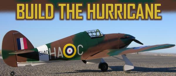
01. The camouflage was airbrushed using Tamiya acrylics, and vinyl graphics were added. The completed model is shown on the flightline, ready for its first mission.
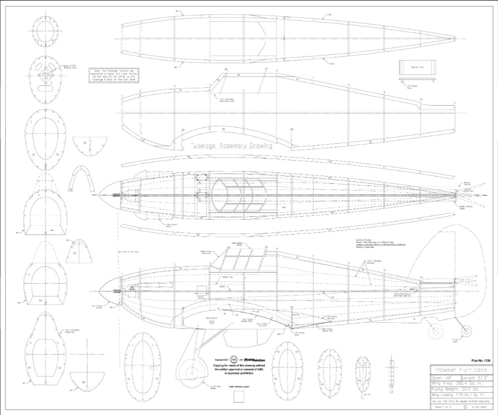
Order Plans from AMA Plans Service
|
|
 |

DOWNLOAD FREE PLANS!
Click here for Tiled plans - 1
Click here for Tiled plans - 2
Click here for Tiled plans - 3
The Hawker Hurricane is a British single-seat fighter built in the 1930s and ‘40s. The Hurricane, although overshadowed by the Supermarine Spitfire, was a capable airplane in its own right, and it was credited with 60% of the Luftwaffe’s losses during the Battle of Britain.
Several variants of the Hurricane were built, including bomber interceptors, fighter bombers, and ground support. A version called the Sea Hurricane was also built for the Royal Navy.
The Hurricane was an offshoot of the Hawker Fury biplane. The new monoplane interceptor was ordered in late 1934 and performed its maiden flight on November 6, 1935. The Hurricane had a 40-foot wingspan, was 32 feet, 3 inches in length, and was powered by a Rolls-Royce Merlin XX 1,185 HP water-cooled, V-12 engine.
Its maximum speed was 340 mph at 21,000 feet and had a range of 600 miles. The rate of climb was 2,780 feet per minute and it had a service ceiling of 36,000 feet. Armament consisted of four 20mm Hispano Mk II cannons and two 250- or 500-pound bombs.
The Model
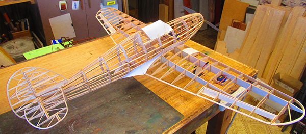
The idea was to build a simple sport scale park flyer that was light enough to fly in smaller venues, but large enough to fly at sanctioned fields. The Hurricane was built with open structure to keep the weight/wing loading down, yet show well both on the ground and in the air.
The 1:10-scale model features a 48-inch wingspan with an overall length of 37.3 inches. Power is provided by a 450-class outrunner motor and guided by four-channel RC incorporating four submicro servos to control the ailerons, rudder, and elevator. Power is provided by a 1,300 mAh 2S LiPo battery.
Building the Hurricane
Make up the bowing patterns for the rudder, elevator, and wingtips from 3/16-inch artist foam board using the provided patterns. Bow the outlines using the part numbers and wood sizes shown.
Fuselage
Construction begins with the fuselage formers. The formers are assembled over the provided drawings and are built up in left and right halves. Because the fuselage is built on the half-shell, the formers halves won’t be joined at the center.
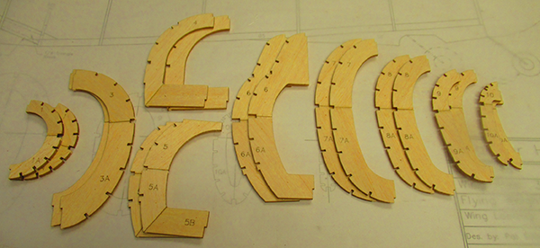
02. To keep the wood grain running in an optimal direction, the fuselage formers are laid out in upper and lower sections. The formers are assembled over the plans in left and right halves.
 03. The fuselage keel and spine are pinned in place over the plans. The chine assemblies are dedicated left and right sides to accommodate the motor’s right thrust.
 04. The fuselage formers are glued in place on the center frame. A squaring block is used to align the formers perpendicular to the frame.
 05. The rudder assembly is built directly over the plans. Shims are used to center the bowed outline on the ribs and spars.
Pin the keel parts B5 to B7, and spine parts B1 to B4, over the plans and then glue the former halves 2 through 11 in place. Build up the chine parts B8 and B10 over the plans, then glue them in place on the formers. Align and glue the 1/8 × 3/16-inch lower canopy rail in place followed by 3B through 6B.
Now former 1 can be glued in place. Lift the frame assembly from the board and glue the formers in place on the other side followed by the B9 and B10 assembly. Now would be a good time to add a couple of stringers above and below the chines to prevent accidentally breaking the formers while the internal components are being set up.
The servos are mounted on 1/8 × 1/4-inch balsa rails glued in place on B8 and B9. The rudder cables are run in along with the plastic elevator pushrod tube. Support using the pushrod stand-off’s (PRSOs) at the rear servo mount beam and at each former in the fuselage. Then, with the controls in and secured, add the remaining WHD and WS stringers. Mount the motor and ESC and test-run the system (without the propeller) to ensure proper direction of rotation.
Rudder
The rudder assembly is built directly over the plans. Pin the hinge spars in place with scrap balsa shims at the top to secure them. Laminate 3 and D3s and pin in place over the plans. Add the bowed outline, followed by all of the 1/16 × 3/8-inch balsa ribs, along with D4 and D5.
Use 1/8-inch scrap balsa shims to hold the outline centered on the ribs and spars. Add the 1/8 × 3/8-inch balsa doubler at the bottom then fit and glue the 1/16-inch square balsa diagonal bracing in place on center.
Remove the rudder assembly from the board, cut the rudder free from the fin, and sand to shape. Drill a .070-inch hole (#50 drill bit) for the toothpick control horn. Cut the toothpick horn 1-1/16-inch long and dry-fit it into the rudder. Cut the hinges using the provided pattern and dry-fit them into the rudder. Bend the tail wheel strut to shape, fit it into the hinge spar, and glue it in place.
Horizontal Stabilizer
Laminate C1 and C2 and pin them in place over the plans. Pin C3 in place over the plans, followed by C4, C5, C6, and C7, using shims to properly space them above the plans. Align and glue the laminated outline in place using 1/8-inch scrap balsa shims to center the outline. Align and glue all of the 1/16 × 3/8-inch and 1/8 × 3/8-inch balsa ribs in place, followed by the 1/16-inch square balsa diagonal bracing.
Remove the stabilizer assembly from the board, cut the elevator free from the stabilizer, and sand to shape. Align and glue C8 and C9 in place flush with the bottom then cut in and dry-fit the hinges in place.
Wing
Cut the wing assembly plans from the plans sheet and tape them together at the centerline. Laminate A1A and A1B in place on A1 to make a one-piece main spar. Laminate A2A on A2 to make the one-piece rear spar. Laminate R3 and R3A, and R4 and R4A together. Dry-fit ribs R1, R2, R3/R3A, and R4/R4A in place on the A1 and A2 spar assemblies. Pin A5 in place over the plans, followed by the 3/32 × 1/4-inch balsa trailing edge (TE) at A5.
At a Glance
Specifications
Wingspan: 48 inches
Length: 37.3 inches
Wing area: 382.4 sq. in.
Flying weight: 20.5 ounces
Wing loading: 7.75 ounces per sq. ft.
Power
- Suppo 2217/9 outrunner motor
- 20-amp ESC with BEC
- APC 11 × 5.5E propeller
- 1,300 mAh 2S LiPo battery
Guidance
- (4) 9-gram submicro servos
- (3) 6-inch servo extensions
- (1) 6-inch servo Y lead
- (1) JR RG612BX full-range receiver or equivalent
Materials List
- (1) 1/64 × 4 × 5-inch birch plywood
- (1) 1/32 × 6 × 12-inch birch plywood
- (1) 1/16 × 3 × 12-inch balsa
- (3) 1/16 × 1/16 × 36-inch balsa
- (18) 1/16 × 1/8 × 36-inch balsa

06. The horizontal stabilizer is built directly over the plans. Shims ensure that the bowed outline is centered on the ribs and spars.
 07. The front and rear wing spars are laminated with plywood stiffeners, making one-piece spar assemblies.
 08. The radiator assembly is built-up and sanded to final shape. The inside should be painted flat black when completed.
 09. The instrument panel hood is cut from file folder paper and glued in place at the front of the cockpit.
Align and glue ribs R1 and R2 in place on A5 and pin the assembly in place. Slip A8 in place between R3/R3A and R4/R4A and seat into the notches. Cut the 3/16-inch diameter wing hold-down dowel to length and glue in place on R1, followed by LE-1 and LE-1A.
Remove the wing from the board and pin the main spars A1 and A2 over the left-hand wing plans. Block up the right side to prevent damage to the spars during construction. Laminate R7 and R7A, and R11 and R11A.
Dry-fit all of the ribs in place on A1 and A2. Fit A3 in place and glue all points of contact. Fit and glue the 3/32 × 1/4-inch balsa TE in place then laminate 2 and LE-2s and glue in place. Align and glue ASM, ASM1, and ASM2 in place. Align and glue the tip bow in place, followed by the 1/16-inch scrap balsa gusset, with the 3/32-inch square balsa tip brace in place, and glued in on the center.

10. The landing gear struts are bent from steel wire and lashed in place on the landing gear mount plates with heavy-duty nylon thread.
 11. The root fairing skins are made from plain copy paper and, when in place, sealed with two coats of nitrate dope.
 12. The exhaust stack was carved from basswood. A silicone rubber mold was made and the stacks were cast in resin.
 13. The Hurricane not only looks good in the air, but it is also a solid, steady flier.
Remove the wing assembly from the board and pin A1 and A2 in place over the right-hand wing plans to build the other wing. Remove the wing from the board, glue A8A in place flush with the bottom of R4/R4A, and sand to rough-shape it.
Align and glue the aileron servos in place on ASM with silicone caulk. When dry, run in the wiring, connect with a Y lead, and secure with WG glued in place, flush with the top of the rib.
Ailerons
Sand a bevel into the bottom of A4 then align and glue AR1 and AR5 in place. Pin the assemblies in place over the plans, and then glue the 3/32 × 1/4-inch balsa TE in place. Align and glue AR2, AR3, and AR4 in place, followed by A7, flush with the bottom of the ailerons. Remove the aileron assemblies from the board, sand to shape, and then cut in and dry-fit the hinges in place.
Fitting the Landing Gear
Bend the main landing gear struts to shape from 3/32-inch diameter steel wire. Tack-glue the struts in place on A8 and lash in place with heavy-duty nylon thread. Harden the lashings with thin CA. Fit the 1/16-inch balsa top and bottom sheeting and glue in place. Now the wing assembly can be sanded to final shape. The landing gear trailing struts will be added after the wing is covered.
Fitting the Wing to the Fuselage
Slip the wing in place and align then drill a 9/64-inch hole for the 8-32 wing hold-down bolt. Remove the wing and harden the hole with thin CA. Tap the hole and reharden with thin CA then tap it again to clean the threads.
Cut the wing root fairing parts using the patterns provided on the plans. Align and glue the front bottom fairing section to WS. Fit the wing back on the fuselage and glue 6C in place at former 6B and the fairing centered on the aft edge of the fairing. Glue the bottom rear fairing in place at 6C with the aft end centered on the bottom stringer. Align and glue 5B in place at WS and the bottom fairing. Remove the wing from the fuselage, and then fit and glue the front and rear top fairing sections in place.
Covering the Model
Do a final detail sanding on the entire airframe then perform a final dry assembly to make sure everything fits properly. Pull the rudder cables through the fuselage and tape them to the control horn. Mark the exact location on the plans where the cables exit the fuselage. When everything is fitting and working properly, disassemble the components and cover the model.
The model can be covered with any of the lightweight iron-on coverings, such as UltraCote ParkLite, Silkspan, or Polyspan and dope. Then, with all of the covering in place, paint and detail as desired and add your graphics of choice. The exhaust stacks can be carved from balsa or basswood. I made one stack then made a silicone rubber mold and cast them with resin. The resin stacks were trimmed to fit and glued in place.
Final Assembly
The wing is bolted in place then the tail section is aligned and glued in place using the wing for reference. The .025-inch steel elevator pushrod was run in and secured with a Z-bend at both ends. The aileron pushrods were set up using .032-inch steel wire in the same fashion. The rudder cables were pulled through the fuselage and secured at the control horn.
The canopy and windshield are cut from .008-inch acetate and glued in place then they are trimmed with vinyl tape. Mount the main and tail wheels, followed by the main gear trailing struts. Make the landing gear doors from 1/32-inch plywood and glue them in place on the main gear struts. Build up the radiator and sand to shape. Paint the inside flat black and glue it in place on the wing centerline.
The receiver is connected, and the control throws are set up as follows:
- Ailerons: 5/8 inch each way with a 70% dual rate
- Elevator: 7/16 inch each way with a 70% dual rate and 20% exponential
- Rudder: 1 inch each way
With everything working nicely, trim the spinner and backplate and glue the spinner cone in place with silicone caulk. Set the center of gravity (balance point on the plans) at 2-3/4 inches from the wing’s leading edge at the root. Use the battery to balance to your best advantage then make the battery tray from light plywood and mount the battery at the appropriate location inside the fuselage. To avoid cluttering the fuselage with a hatch, the wing is removed via one bolt to access the battery. The battery is secured to the tray with Velcro.
Flying the Hurricane
The Hurricane was surprisingly stable and easy to fly. With full throws, the ailerons and rudder are quite docile, but the elevator, although manageable, is lively, so a bit of exponential is not a bad idea.
With the recommended motor, propeller, and battery setup, the model has plenty of power and will lift off and climb nicely at slightly above half throttle. Using proper power management, the 1,300 mAh battery will deliver 8- to 10-minute flights.
With its light wing loading, the model will slow down nicely, and although it will stall, it doesn’t drop a wing but rather mushes along in a sinking nose-up descent. To set up the landing, the approach is done slightly nose-up carrying a bit of power.
I found it best to wheel-land because, at a full stall, the sink rate can be extreme. Simply flying the model all the way down seems to work best.
And with that, you’re ready to reenact the Battle of Britain at your local flying site.

This Month's Issue
Join the AMA
![]()


Add new comment