A tiny black box for every model
By Bruce Walker [email protected]
Photos provided by the author
As seen in the August 2026 issue of Model Aviation.
As an RC pilot, when I land, I always want to know how fast I flew, particularly with EDF jets. I want to be able to compare different airplanes, propellers, EDF fans, power systems, and even batteries. Of course, there are always bragging rights as to how fast I flew! Unfortunately, many of my airplanes—in particular, most EDF and BNF airplanes—do not have a means to record aircraft speed.
There are a few traditional ways to measure speed. One is having a friend with a Doppler radar gun. (Doppler is the change in frequency from relative motion.) A problem with using radar is that the airplane must fly directly toward the radar to get an accurate measurement; otherwise, you are only measuring a fraction of the actual speed. Because flying an airplane directly at humans is not a safe proposition, this is not a recommended solution. The other problem is that I don’t have a friend with a Doppler radar gun. (You could also consider Doppler analysis from the sound of the aircraft, but that has limitations, such as the flight path, wind effects, and background noise, and it requires constant throttle.)
How Does GPS Work?
When the Soviet Union launched Sputnik in 1957, a couple of American physicists discovered that by measuring the satellite’s radio signals from locations on Earth, the satellite’s position could be determined. This was the beginning of satellite-based navigation. GPS solves the inverse of this problem. By knowing the position of several satellites, with each transmitting a unique signal, the position of a receiver on Earth can be determined. GPS determines the distance from each satellite to a receiver by measuring the time it takes for the satellite’s signal to arrive at the receiver (distance = speed of light × time).
While three satellites can provide a position fix by the intersection of the three distances (a process called trilateration), the timing error at the receiver is too large for an accurate fix; thus, four satellites are required to determine the position (latitude, longitude, and altitude) and the accurate time. How accurate of a time measurement is required? Well, every one billionth of a second of error in time corresponds to about a foot of distance error!
A parameter called Horizontal Dilution of Precision (HDOP) is a measure of the geometric arrangement of the satellites, which, in turn, is a measure of the horizontal position accuracy. For HDOP, smaller is better, with less than 2 being desired. While HDOP is displayed on the GPS Flight Recorder when obtaining initial fixes, you don’t really need to worry about HDOP unless you are having problems with poor antenna placement. HDOP is just shown at the startup to indicate the quality of the fix that you are getting.
To provide 24/7 worldwide coverage, GPS uses a network of 24 satellites that are transmitting signals to receivers on the ground. Another half-dozen or so satellites serve as on-orbit spares. When your GPS receiver is turned on, it typically requires a minute or two to acquire the signals from at least four satellites and determine your location. The accuracy of your location is largely determined by the number of satellites you receive and their geometry relative to your position. This is why it is important to provide the GPS antenna with the most unobstructed, horizon-to-horizon view possible.
To provide an accurate GPS location, there are many errors that must be compensated: clock timing errors, signal arrival time errors, ionospheric effects, satellite location (ephemeris) errors, tropospheric (weather) effects, and many other errors—including compensation for relativity. According to Einstein’s theory of relativity, since the satellites are moving faster than the GPS receiver (which is usually the case), the satellite clock is moving slower, and because the satellites sense lower gravity in orbit, the satellite clock is moving faster (which dominates).
If these relativity errors were not compensated, the GPS location would be off by approximately 6 miles per day. Yes, Einstein was correct! Only through a complex process of correcting all of these various errors to the extent possible is a location accuracy of close to 16 feet (5 meters) achieved. As mentioned in the main article, the satellite geometry does not yield as accurate of an altitude measurement, and altitude errors of +/- 100 feet or more can occur.
GPS was initiated by the U.S. Department of Defense in 1973 and became fully operational in 1995. It remains an amazing, impressive navigation system. Ongoing improvements continue to be implemented in the system, so performance will keep getting better. Today, there are a number of satellite navigation systems collectively known as the Global Navigation Satellite System, or GNSS. They include GPS (US), GLONASS (Russia), Galileo (European Union), and BeiDou (China). In addition, there are regional systems such as QZSS (Japan) and IRNSS (India).
Many "GPS" receivers, including the one in the GPS Flight Recorder, are actually GNSS receivers and use satellites from two or more of these constellations, providing improved accuracy and a faster fix time over using just one system.
Another option would be to use a pitot tube to measure the air speed. This requires modification of the aircraft for installation, and then either a telemetry receiver or some onboard means to record the speed. This is a viable option, but it is somewhat difficult to place one in each airplane in your hangar.
That leaves GPS, the Global Positioning System. GPS does not directly measure speed; it measures the location. If the location changes over time are used to calculate speed, the answer is often less accurate. Instead, most GPS receivers measure Doppler from each satellite signal to calculate an accurate speed measurement. If the receiver is listening to eight satellites, it’s like having eight police radars tracking your airplane!
What started as a simple project of "How fast did I go?" grew into a much more useful flight recorder that can work with any model, regardless of the receiver brand or telemetry capability.
What the GPS Flight Recorder Captures
Rather than streaming data to the transmitter, the GPS Flight Recorder records the most important flight limits and displays them after landing. If you have a GPS receiver on the airplane with the ability to record the maximum speed, why not include other information that is valuable to have, particularly on airplanes where telemetry is not available, such as:
- The cumulative number of flights on that airplane
- The minimum receiver voltage during the flight
- The maximum speed during the flight
- The maximum altitude during the flight
- The maximum distance flown from turn-on
- The total distance flown (odometer)
GPS provides all of the parameters listed above except for the minimum receiver voltage. You typically do not need these six parameters during the entire flight—only the limits after the flight, maximum or minimum.
I desired a solution that would work in any RC platform, regardless of the receiver. This article describes the design and operation of the GPS Flight Recorder, which records and displays the six parameters listed above.
Small Enough to Fit Anywhere
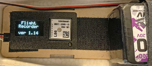
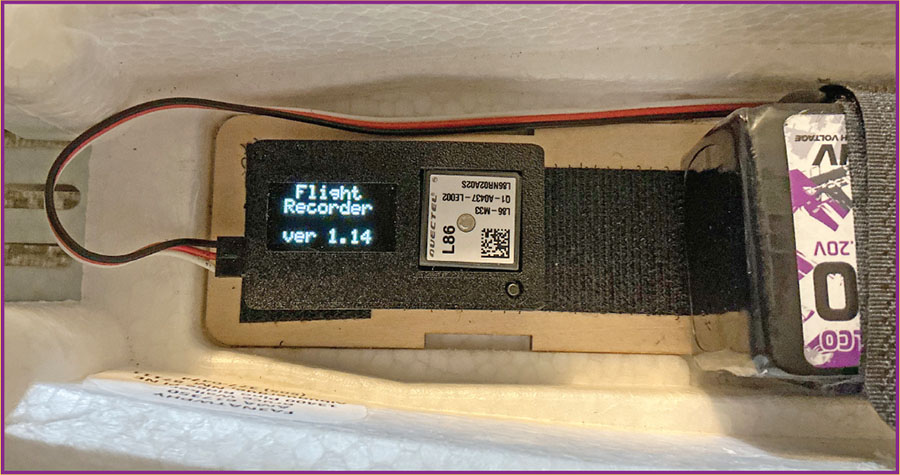
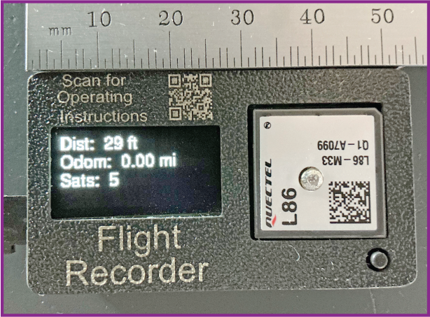
Figure 1 shows the GPS Flight Recorder, a custom electronic module that is physically small (1.25 × 2.125 × ½ inches), lightweight (0.84 ounces, or 23.7 grams), and easily fits in most any aircraft, drone, helicopter, car, boat, etc.
The only external interface that is required is voltage from a receiver (4 to 9 volts direct current), which can be from a spare receiver channel, a Y connection, or even a bind or data port. Because it only receives voltage from the receiver, it is compatible with any receiver, regardless of the manufacturer. If it’s desired, a separate battery can be used for power, although the "minimum receiver voltage" will simply reflect the minimum voltage of the battery.
The GPS Flight Recorder uses a GPS module with a built-in antenna, an ATtiny microcontroller, and a small OLED display to present the results. The software is written in C++ in an Arduino-integrated development environment.
Startup: Getting a Good Fix
When it’s first powered on, the GPS module needs time to "lock on" to satellites (typically a minute or two) for the first "fix" of the day. When at least four satellites are detected—the minimum required to establish a three-dimensional position—a fix is achieved. Subsequent fixes on the same day are usually much faster. (See the sidebar on the second page of this article for more information about GPS.)
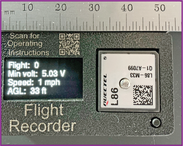
Figures 3 and 4 show the GPS Flight Recorder displays after this startup process is completed. To keep the display readable, only four values are displayed at a time because of how small the GPS Flight Recorder is. A single push button steps through four different displays; the first two displays show the six parameters and the number of GPS satellites in imperial units, and the next two displays (not shown) show the same data in metric units. Whatever page you were using last is where it starts up the next time.
Flight Number, Minimum Voltage, and Why It Matters
The first parameter shown is the aircraft’s cumulative flight number, which is valuable for addressing maintenance concerns. Having a flight count for each airplane also addresses my need for keeping track of how many flights are on each aircraft! Once a certain altitude and speed are reached, the flight number is increased. If it’s ever desired, the flight number can be reset to zero by holding down the push-button switch when it’s powered on.
The next parameter is the minimum receiver voltage during the flight, arguably one of the most valuable—and often overlooked—pieces of data. The receiver voltage is sampled at more than 10,000 times per second, which is fast enough to capture any voltage glitches or dropouts. Knowing the minimum receiver voltage helps diagnose flight anomalies and prevents future receiver brownouts.
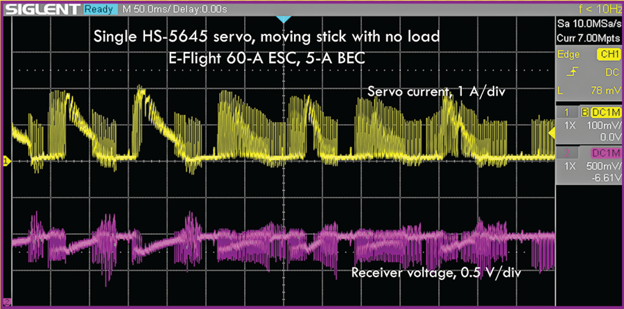
Many battery eliminator circuits (BECs) are not built to handle the high-current spikes that are generated by digital servos and occur even when there is no load on a servo. As an example, Figure 2 shows a single Hitec HS-5645 digital servo without a load. The top curve shows the servo’s current versus time, with current peaks of up to 2 amps. The bottom curve shows the voltage output from a 5-amp BEC powering the receiver versus time. With only one servo operating and without a load, the BEC voltage varies by almost 1 volt peak-to-peak.
Frankly, most BECs are not designed to handle these peak loads, certainly not from multiple servos under load. When using a battery instead of the 5-amp BEC, the servo current peaks are 4 amps versus only 2 amps with the BEC. Clearly, the BEC is struggling with only one unloaded servo. Knowing the minimum receiver voltage during a flight provides some assurance that your receiver power source is adequate. The GPS Flight Recorder would have shown a low receiver voltage to indicate a potential problem.
Speed, Altitude, and Distance: What GPS Can (and Can’t) Do
After the minimum receiver voltage, the display shows the maximum speed and maximum altitude during the flight. The GPS Flight Recorder assumes that the airplane is on the ground when it’s turned on (usually a good assumption!) and uses the altitude measurement at that time to determine the maximum above-ground-level altitude during flight. While GPS usually provides a good horizontal position fix (16 feet or so), unfortunately, the altitude measurement is not as accurate and can sometimes be off by +/- 100 feet or more.
As shown in Figure 4, the display provides the maximum distance during the flight from where it was turned on. This is useful if there are any range or field boundary concerns. Just for fun, the GPS Flight Recorder also displays an odometer that shows the total distance that was flown. It is amazing how many miles are flown on a typical flight. Lastly, the number of satellites providing the GPS fix are displayed as well.
Availability
I originally developed the GPS Flight Recorder for my own models and a few local flying friends. Recently, a fellow RC modeler, Ken Elder—who I mentioned in the May "Worth a Closer Look" about the Precision Extension Tester—took an interest in the design. Ken owns an electronics manufacturing company, PE Manufacturing. The GPS Flight Recorder is now in production and available to any modeler who wants post-flight data about their airplane’s performance. It sells for $59.95 through Ken’s company and can be ordered on its website, the link to which can be found in "Sources."
SOURCES:
PE Manufacturing





Comments
Add new comment