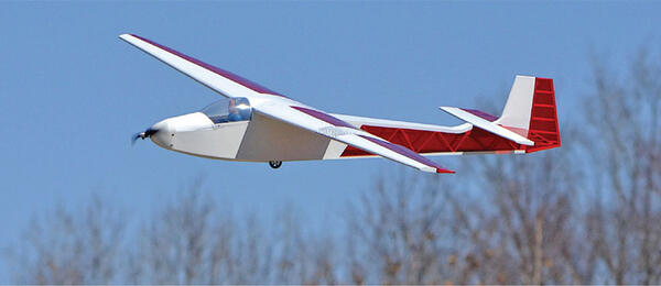
A hidden gem of British aviation history gets an electric revival
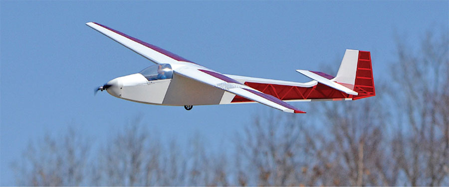
The Value Planes T-45 Swallow is a sport-scale model with a wide performance envelope.
I CONSIDER MYSELF to be a fairly savvy enthusiast of aviation history. Until recently, however, I was completely oblivious to the Slingsby T-45 Swallow. The Swallow is a simple British glider that was designed in the 1950s. A little more than 100 units were produced, most of which found their way to Soaring clubs in the U.K., the US, and beyond. Some Swallows were even conscripted for military uses.
The Value Planes rendition of the T-45 is a lasercut kit with balsa and plywood components. The completed four-channel model spans approximately 71 inches. While the full-scale T-45 is a pure glider, this RC model can also be equipped with an electric propulsion system. In fact, the T-45 is available from Hobby Club (the US importer of this kit) with an optional Power Pack that includes four 9-gram servos, a 2214/10T 1,400 Kv brushless motor, a 9 × 5 folding propeller, and a 30-amp ESC. The example I built for this review uses the Power Pack components.
Building the T-45 Swallow
The kit includes full-size printed plans and a printed instruction manual. I used medium CA glue for most of the construction steps. The only exceptions were that I used Titebond II wood glue when I sheeted the wing and horizontal stabilizer, and 5-minute epoxy for the motor mount and servo mounts.
Construction begins with the fuselage. At a glance, the rear fuselage appears to be a truss made with meticulously angled segments of balsa sticks. That’s a clever illusion. The fuselage is actually a simple box structure with plywood sides. The parts utilize tab-and-slot alignment to ensure that the resulting fuselage is square and true.
I ran into a few hiccups when I was working on the wing center section that is built into the fuselage. The manual directs you to install a fairing that blends the area behind the cockpit with the top of the wing center section. Since no part number is mentioned in the manual or the plans, I assumed that the fairing should be made from scrap balsa that is found on the part sheets. I made the fairing from scratch, only to discover later that doing so was unnecessary. The kit includes a laser-cut fairing, but it doesn’t have a part number or markings. I could have saved a lot of time if I had been aware of the kit-provided part. This scenario was repeated verbatim with the bottom sheeting for the forward fuselage.
Vacuum-formed plastic parts are included for the nosecone and canopy. The parts fit well, but they are not perfectly clear. They have a slight whitish haze to them. The canopy gets installed on a removable hatch that provides access to the model’s electronics. I think it looks nice to have a pilot in the cockpit of a Scale model, so I used scrap balsa to install a false floor on the hatch and added a lightweight pilot bust from my stash of shrunken heads.
The tail feathers are built entirely from laser-cut parts—even the sheeting on the horizontal stabilizer is precut. I assembled these parts over the plans and everything fit as indicated. A lot of sanding is required to shape the leading edge (LE) and the trailing edge of the tail feathers. I used 80-grit sandpaper on a DU-BRO 11-inch Kwik Sand Hand Sander for most of this shaping.
Despite the sheer number of ribs in the Swallow’s long, tapered wing, assembly is quick and straightforward. As with the tail feathers, the wing panels are also built over the plans. All of the parts fit together well. Each aileron has a dedicated 9-gram servo. The mounts for these servos get glued into the wing structure with the servos installed. Minor surgery will be required if I ever need to adjust or replace either aileron servo. I used a 24-inch servo extension on each of the aileron servos.
After I had completed the final step in the instruction manual, the Swallow still required a bit more work. Some elements of the assembly process are just not covered in the instructions. While this could be a significant roadblock for inexperienced builders, it should not be an issue for any modeler with a few prior kits on their résumé.
Most of the missing steps are related to installing and setting up the control system. The kit includes the hardware that is needed for these tasks, such as pushrods, control horns, and CA-type hinges. If you purchase the optional Power Pack, you will get the rudder and elevator servos as well.
Mounting the brushless motor required a little bit of improvisation. The kit includes two plywood discs that are obviously intended to be used for the motor mount; however, the mount required an additional 1/2 inch of thickness to properly position the motor in relation to the plastic nosecone. I laminated two pieces of scrap 1/4-inch balsa to create a 1/2-inch spacer. I epoxied both plywood discs to the front of this spacer then trimmed away the excess balsa with my scroll saw. The result was a cylindrical motor mount that is approximately 3/4-inch long. I epoxied this mount to the front of the firewall to achieve the proper positioning and spacing of the motor.
The instructions indicate that the clear nosecone is made of PVC. I was concerned that normal spray paint would not adhere well. Using water-based paint that is intended for polycarbonate RC car bodies, I painted the inside surface of the nosecone white. It has been holding up perfectly thus far.
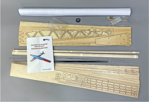
The Swallow kit includes laser-cut components, full-size plans, and a selection of hardware.
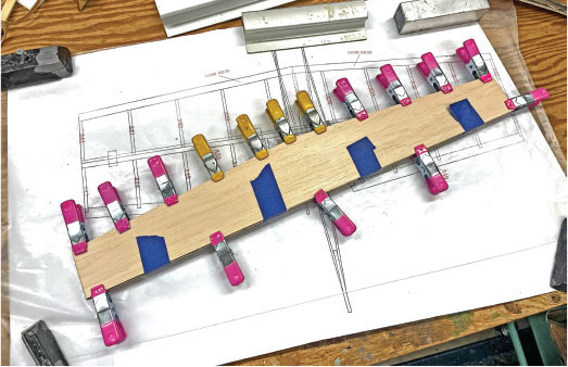
The T-45 utilizes many traditional model-building techniques. Here, clamps and tape were used to hold the horizontal stabilizer sheeting in place while the glue dried.
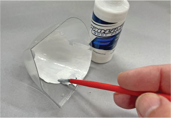
The author used paint that is intended for RC car bodies to color the clear, plastic nosecone.
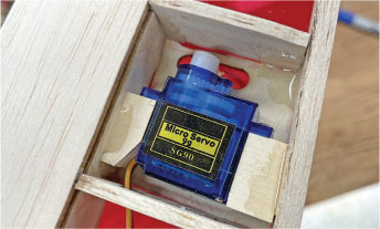
The control surfaces use 9-gram servos. This servo actuates the right aileron.
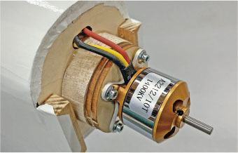
The 1,400 Kv brushless motor that is provided with the Power Pack is a good match for this model. Note the improvised balsa and plywood motor mount.
With the full-scale Swallow’s wide use in multiple countries, there are numerous scale color schemes that can be chosen for this model. I went in the opposite direction with a decidedly nonscale motif that showcases the model’s wooden airframe by using opaque white and transparent red iron-on film. A stripe of glittery silver vinyl on the left wing half helps me maintain orientation in flight. Clear packing tape works well to secure the wing panels to the fuselage for flight.
Configuring the T-45’s Power System
The folding propeller that is included in the Power Pack has an aluminum yoke with nylon blades. The blades pivot on 3 mm screws that pass through the yoke. The holes in the blades were undersized, so I carefully enlarged them with a 3 mm drill bit. I then installed the blades into the yoke, using nylon washers to eliminate any side-to-side play between the blades and yoke.
I prepared the propeller assembly for balancing by lightly tightening the lock nuts on the pivot points to prevent the blades from pivoting freely. I then extended the blades and balanced the assembly in my DU-BRO Tru-Spin Prop Balancer, just as I would for a standard, non-folding propeller. I added tape to the lightweight blade to achieve balance then loosened the lock nuts just enough to allow the blades to pivot freely again.
For a folding propeller to work properly, the ESC must have a brake function that activates when the throttle is at idle. This will stop the propeller from spinning in flight and allow the blades to fold back. The ESC that came with my kit did not have the brake feature enabled, nor did it include instructions for changing any settings. Thankfully, this ESC can be programmed through the radio transmitter, and it uses the same menu found on many other ESCs. The companion video for this review, found on AMA’s YouTube channel, includes a short tutorial on setting the ESC’s brake function. Note that physical programming cards intended for other ESCs are not necessarily compatible with this one. I would not try to attempt that strategy.
I suggest adding holes for cooling air to reach the electronics. I cut a small hole in the nosecone then drilled holes in the firewall for the air to pass through. Lastly, I removed an area of covering on the bottom of the fuselage, near the tail, for air to escape.
For the Swallow’s radio system, I chose a Futaba T14SG transmitter with an R617FS receiver. The model is powered with a Spektrum three-cell 2,200 mAh 50C Smart G2 LiPo battery. It is secured to the battery tray with hook-and-loop tape. At full throttle, the power system pulls approximately 23 amps and produces 270 watts of power. Factoring in the Swallow’s 2.4-pound flying weight, my airplane has a comfortable power loading of 113 watts per pound.
Flying the T-45 Swallow
The plans show the T-45’s center of gravity (CG) at 86 mm behind the wing’s LE at the root. I wanted a more conservative CG location for my initial flights with the Swallow, so I set the balance point at 65 mm behind the LE. I like the way it flies with this CG, so I have not adjusted it any further.
An easy hand launch will get the Swallow airborne. The power system provides a strong climb rate—just do not expect a rocket-like vertical departure. If Soaring is your thing, one trip around the pattern will get you to a nice altitude where you can shut down the motor. I’m not a great glider pilot, but I do enjoy stretching out the Swallow’s glide as long as I can before powering up for another climb to altitude.
The manual does not provide suggested control throws. After some experimentation, I have found that I like 25° of throw in each direction for the ailerons, 15° for the elevator, and 20° for the rudder. I also have 25% exponential programmed into each of those channels.
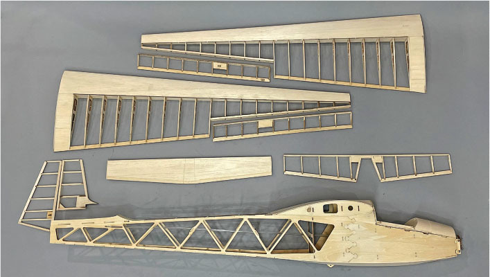
In this view, the completed airframe has been sanded and is ready for covering.
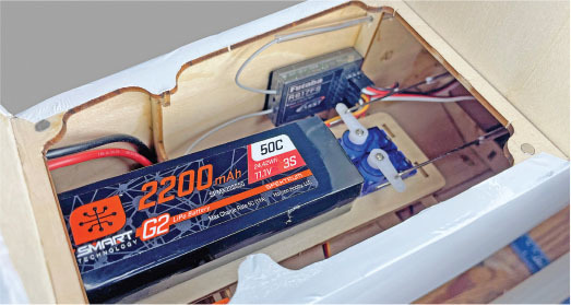
Removing the canopy allows ample access to the battery tray and onboard radio gear.
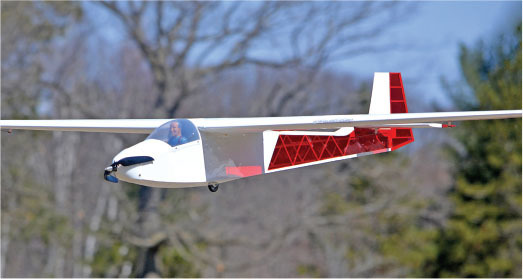
With the motor off and the propeller folded back, the Swallow maintains energy very well.
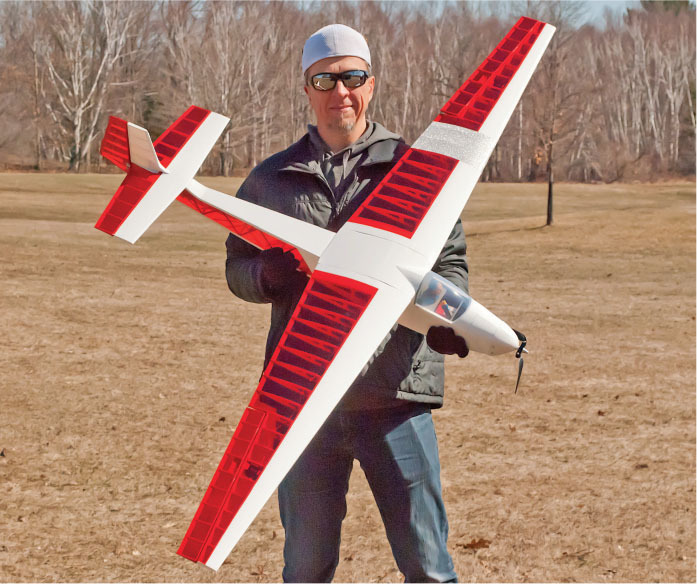
While Terry could have chosen a scale color scheme, he went with translucent covering to show off the Swallow’s wooden airframe.
I was surprised by the maneuverability of the Swallow. It is capable of basic four-channel aerobatics, such as loops, rolls, and inverted flight. I like to mix up my flights with a blend of Soaring and goofing off. Both types of flying are fun with this model.
With the CG and control throws that I use, the T-45 will try to tell you that a stall is coming. If you hold back-pressure on the elevator, the aileron response will get sloppy as the airplane nears stall speed. In my experience, a full stall is indicated by an obvious drop of one wing half. This wing drop will progress into a nice spin until you neutralize the elevator. The Swallow recovers to straight-and-level flight very quickly.
The T-45 has a somewhat boxy appearance, but it is deceptively sleek. This design retains energy very well. In fact, I overshot my first few landing attempts because the model kept gliding far beyond my expectations. I was very glad that I had a motor so that I could climb out and try again! I have since discovered that I can kill energy on a hot approach with a mild sideslip. An alternate strategy is to feed in just enough throttle to unfold the propeller blades and utilize the drag of the propeller disc.
All of my landings thus far have been on grass runways. I was somewhat concerned that the single wheel protruding from the model’s belly would get tangled in the grass, but this has not been an issue. With a smooth landing, the model rolls to a noneventful stop. The wheel has also proven to be strong enough to withstand my not-so-smooth landings.
Final Approach
The Value Planes Slingsby T-45 Swallow offers a chance to build a sport-scale rendition of a unique and rarely modeled subject. While I would not recommend this kit for inexperienced builders, veteran builders will have no trouble at all. Best of all, the completed model is an attractive, well-rounded performer in the air.
SOURCES:
Spektrum






Comments
Add new comment