The full-scale Beechcraft AT-10 began under the designation of the Model 25 and was designed in 1940 to meet the U.S. Army Air Corps (USAAC) requirement for a trainer suitable for training bomber and transport pilots in aircraft with multiengines and retractable landing gear.
The design required the use of nonstrategic materials because of possible shortages of aluminum during the war effort. Model 25 was built primarily of wood and was presented to the USAAC in the same year. The prototype crashed on May 5, 1941.
Beechcraft began redesigning the aircraft the following day, designating it as Model 26. It made its first test-flight on July 26 of the same year. It was delivered to the USAAC under the designation of AT-10, and later named Wichita after Wichita, Kansas, where the airplanes were manufactured. By the end of 1942, 748 AT-10s had been delivered by Beechcraft, and by 1943, a total of 1,771 airplanes had been built. Additionally, 600 AT-10s were built by Globe Aircraft before production ceased in 1944.
The AT-10 had a 44-foot wingspan, an overall length of 34 feet, 4 inches, and a maximum takeoff weight of 6,130 pounds. Two Lycoming R-680-9 air-cooled radial engines, rated at 295 hp each, provided power for a top speed of 198 mph, a range of 770 miles, and a service ceiling of 16,900 feet.
The Model
The Beech AT-10 Wichita model was designed with a 50-inch wingspan at 1:10.55 scale and an overall length of 36.5 inches. Power is provided by a pair of counter-rotating Suppo 2212/15 outrunner motors and a 2,000 mAh 2S LiPo battery. Construction is primarily of balsa and plywood in the typical stick-and-tissue construction style.
The wing is built around an eggcrate style of construction to keep the assembly strong, yet quick and easy to build. In keeping with the park-flyer style, the design incorporates bowed outlines for maximum strength and minimum weight. The battery is accessed through a removable canopy secured with rare-earth magnets.
Guidance is by way of a simple four-channel radio that includes rudder, elevator, aileron, and throttle control. With a flying weight of 33 ounces and a wing loading of only 13.3 ounces per square foot, the model can be easily flown in smaller venues.
All of the patterns are provided for cutting the shaped parts; however, for those who prefer to use laser-cut parts, a wood and plastic pack is available from Manzano Laser Works.
Building the AT-10
Construction begins with the smaller subassemblies so that they’ll be handy when assembly gets underway. The wingtips, stabilizer tips, and rudder outlines are bowed over forms made from 3/16-inch artist’s foam board using the provided patterns.
The main landing gear and tail wheel struts are bent to shape from steel wire, also using the patterns provided. The front and rear wing spars are assembled according to the plans. The tail wheel mount is constructed using former TWM (tail wheel mount), TWMb, and 3/32-inch outer-diameter (OD) brass tubing. The tail wheel control horn is built up using .015 × 1/4-inch brass and a 1/16-inch wheel collar that are soldered together. Using the fuselage former cross-sectional plans drawings for reference, fit and glue the 1/16 × 1/8-inch balsa stiffeners in place on formers 4 through 9.
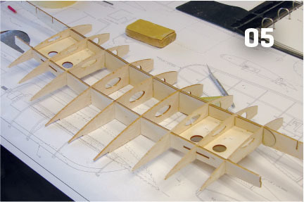
01. The AT-10 is finished and ready to fly.02. The main landing gear and tail wheel struts are bent from steel wire using patterns provided on the plans.03. The wingtips, elevator tips, and rudder outlines are bowed using strip wood over artist’s foam board patterns.04. The main and rear wing spars are assembled by laminating the plywood doublers over the balsa spars.05. Wing assembly begins by dry-fitting the spars, landing gear mount plates, and ribs in place. The assembly is then aligned and pinned in place over the plans and glued together.06. The main landing gear struts are lashed in place on the mounts with heavy-duty nylon thread then hardened with thin CA glue.07. The wing assembly is complete and sanded to shape. Balsa blocks are used to shape the inboard and outboard ends of the aileron bay.
Building the Tail Section
The rudder and horizontal stabilizer assemblies are built directly over the plans. Supporting the leading edges (LEs) on center are 1/8-inch thick shims. Shims that are 5/32-inch thick are cut from 1/8-inch balsa to support the elevators’ TEs.
Rudder
Pin hinge spars D1 and D2 in place over the assembly plans with the notches facing up. Glue the 1/8-inch square balsa doubler on the center of D3 then drill the 5/64-inch holes for the toothpick alignment pins.
Glue the D3 assembly in place followed by D6 and the 1/8-inch square balsa LE, using the shims for alignment. Pin the bowed outline in place over the plans using the shims, and then glue D7, D8, and D9 in place, followed by all of the ribs.
Remove the assembly from the board and glue the 1/4-inch square balsa and two D14 pieces in place as shown. Fit and glue the 1/16-inch square basswood diagonal bracing in place on center and sand to shape.
08. The basic engine nacelle frames are built upside down over the plans.
Using the provided pattern, cut the hinges from CA hinge stock and dry-fit them into the rudder. Drill the 5/64-inch hole for the control horn, create the toothpick horn using the diagram provided, and dry-fit the horn in place.
Horizontal Stabilizer
Laminate C1 and C2 together and pin them in place over the assembly plans with the notches facing up. Place scrap balsa shims under the outboard ends of the spar as shown to ensure that it remains level. Pin the 1/8-inch square balsa LE in place over the plans using the shims as shown, followed by the C6s and each of the ribs. Pin C3 in place over the plans then the trailing edges (TEs), shims, and each of the ribs. Fit and glue the C5s and tip bows in place, followed by the 1/16-inch square basswood diagonal bracing glued in on center. Remove the assembly from the plans and sand it to shape. Cut the hinges from hinge stock and dry-fit them in place.
Wing
Cut the wing plans from the plans sheet and tape them together at the center to form a one-piece assembly. Dry-fit ribs R1 and R2 onto the rear spar, fit it in place on the main spar, and pin it in place over the plans.
Fit and glue WHD and the 3/32 × 1/4-inch balsa TE in place. With everything properly aligned, glue each point of contact.
09. The engine nacelles are glued in place on the wing sheeting. The motors are mounted and the ESC and wiring are installed and routed through the wing.10. The tail fairing blocks are carved from blue foam and fitted onto the fuselage. The upper block won’t be glued in place until the horizontal stabilizer is glued in after the frames are covered.11. The windshield assembly also acts as the battery access hatch. Parchment paper is used to prevent the hatch from sticking to the fuselage frame when the magnets are glued in place.12. With all of the framing and sanding complete, assemble the model to ensure that all of the major components fit properly and that everything works before the frames are covered.
Unpin the center section from the board and rock the wing onto the left panel. Fit and glue MGM and ribs R3, R4, R5, and R6 in place on the front and rear spars, followed by the 3/32 × 1/4-inch balsa TE. Pin A7 in place, followed by A5 and each of the remaining ribs. Laminate two LE Os and glue them in place. Align and glue the tip bow and gusset G in place. Unpin the wing from the board and rock the assembly over to the right panel to assemble the other wing.
Remove the wing assembly from the board. Laminate two LE-Is and glue them in place. Fit, position, and glue ASM, ASM1, and ASM2. Lash the landing gear struts on MGM using heavy-duty nylon thread and harden the lashings with thin CA. Tweak the struts as needed so that they’re parallel as they exit the bottom of the wing when viewed from the front.
Fit and glue R4A and the 1/8 × 1/4-inch balsa supports in place at R3 and R5 using the rib drawings for reference. Now the top and bottom nacelle sheeting can be trimmed and glued in position. Fit and glue the balsa blocks in place at the ends of the aileron bay and at the wing hold-down bolt plate then sand the wing assembly to shape.
Ailerons
Using the R7 rib plans drawing for reference, sand a bevel into the bottom of A8. Align and glue AR1 and AR6 in position. Pin the 3/32 × 1/4-inch balsa TE over the plans, then pin A8 in place and glue the ribs to the TE. Fit and glue the remaining ribs in place, followed by A6 flush with the bottom of the aileron. Remove the aileron assembly from the board and sand to shape. Repeat the process to build the other aileron. Cut the hinges from hinge stock and dry-fit in place, again using the R7 rib detail plans drawing for reference.
13. The windshield/battery hatch assembly is painted, the glazing glued in place, and the trim added using a vinyl trim sheet.14. After the frames were covered, vinyl decals from Callie Graphics were added. The rudder trim is Microlite applied using the Windex method.
Fuselage
Build the fuselage side frames directly over the framing plans drawing. PRG will be glued to the righthand fuselage frame, flush with the outside edge. To join the frames, begin by pinning the 1/8-inch square balsa bottom crosspiece over the plans at the back edge of B5. Position, align, and glue B6 on one of the fuselage sides perpendicular to B1, then pin that side in place over the framing plan right side up.
Align the other fuselage side with B6 and glue it in place at B6 and the bottom crosspiece. Align and glue formers 2 through 6 in place on the top of the frame. Pull the side frames together at the aft end and glue the tail wheel mount in place, followed by formers 7 through 10 and the bottom crosspieces. Laminate two B3As together, sand the bevel as shown on the top view, and then glue it in place.
Finally, to prevent breaking the formers, add the two middle 1/16 × 1/8-inch balsa stringers. Remove the frame from the board and fit and glue B4 and B5 in place, followed by the remaining top stringers.
To build up the front-end assembly, pin former 1 flat on the board. Using the nose assembly detail plans-drawing for reference, fit the top former A, bottom former H, and two side formers D in place on former 1A. Fit the assembly into the notches in former 1, align them, and glue them in position. Fit and glue each of the remaining formers in place. Remove the assembly from the board and glue it to the fuselage main frame assembly, followed by formers B2. Sand the assembly to rough shape then cut the fill blocks from soft balsa or blue foam. Glue the blocks in place and sand the assembly to the final shape.
Use the pattern provided to shape the tail fairing block from either soft balsa or blue foam and drill the two 5/64-inch holes and the 3/32-inch channels for the rudder pull-pull cables in the locations shown.
Build up the canopy assembly according to the detail drawing and glue in the magnets that will secure the canopy. Make the windshield from .008-inch acetate and glue it in.
Mounting the Wing
Align, position, and glue the two B5As in place on the top of B5. Fit the wing into the saddle and tape it in place. Working through the holes in formers 1 and 1A, drill holes in the LE for the 3/16 hold-down dowels. Remove the wing and glue in the dowels. With the wing in position on the fuselage, drill the 9/64-inch holes in B5 and tap for the 8-32 hold-down bolts. Remove the wing, harden the threads with thin CA glue, and re-tap the holes.
15. After the engines are detailed and all of the decals and trim are added, the model is balanced, the radio system installed, and the control throws are set up.
Installing the Servos
With the servo arms in the neutral position, glue the aileron servos in place on ASM using silicone caulk. When dry, run in the extensions and bring them out through the center section.
Fit and glue the rudder and elevator servo mounts into the fuselage as shown. Mount the rudder servo on center and the elevator servo on the right side. Run in the elevator pushrod tube and support at PRG at the rear, front, and each fuselage upright with a PRSO. Mount the tail wheel strut and run in the pull-pull cables using the routing diagram for reference and tie them off at the control horn.
Building the Nacelles
The nacelles are mirror images of one another. Begin by pinning N1 and N2 over the assembly drawings. Glue the 3/32 × 1/4-inch balsa stiffener in place on N7 and glue formers N5B, N6B, N7, and N8 in place, being careful to properly orient the stringer notches. Glue N4 in place then remove the assembly from the board and glue in formers N5T and N6T. Dry-fit N3 in position. Glue all of the top stringers in place at formers 5 and 6. Pin the assembly into the board with formers 5T and 6T off the edge.
Fit and glue all of the bottom stringers in place. Make the fairing blocks from soft balsa or blue foam, glue them in place, and sand to shape. Build up and glue the motor mount in place, then build the other nacelle, but be sure it’s a mirror image.
Sand the nacelles to shape then position, align, and glue them on the wing. The landing gear should exit the nacelle on the inboard side of N4. The LGF is then glued on the bottom as shown, followed by N3 on the top. Make up the cowling mounting blocks and glue them in place as shown. Paint and detail the cowlings and engines (Park Flyer Plastics, parts CW4-A and 1027-12 if laser-cut parts aren’t used) to suit and mount them with leftover servo screws.
Mounting the Motors and ESCs
The motors are mounted on the motor mounts and the ESCs are inserted into the nacelles. Run the wiring in through the holes in the bottom sheeting and ribs and run it out through the center section. Secure the wiring at R1 with WGF and WGR.
Test-run the motors to ensure the proper direction of rotation. If counter-rotating propellers are used, the left motor should turn clockwise and the right one counterclockwise (when viewed from the rear). In other words, both propellers should turn inward at the top.
Covering the AT-10
Before covering the model, perform a final detail sanding to remove any irregularities in the frame. It’s a good idea to scallop formers 3 through 9 and N6B and N7 between the stringers to eliminate bumps in the finished covering. If you use iron-on Mylar, choose the lightest that is available for the best results. Apply the covering according to the manufacturer’s instructions.
Final Assembly
Bolt the wing in place and mount the horizontal stabilizer, tail fairing block, and vertical tail using the wing for alignment reference. Run in the .025-inch wire elevator pushrod and connect with Z-bends at both ends. The rudder cables are run in and connected to the toothpick control horns. Form the aileron control rods from .032-inch steel wire using a Z-bend at both ends.
Create all of the nacelle fairings from file folder paper. Glue them in place and paint them to match. Make up the main wheel keepers according to the detail plans drawing and mount the wheels. From here you can add the details that you like.
When completed, use the battery to your best advantage to balance the model inverted at the location shown. Secure the battery on a light plywood tray using Velcro. Set up the control throws as follows: aileron 5/8 inch each way (measured at the inboard end) with 70% dual rate; elevator 5/8 inch each way with 70% dual rate; and rudder 1 inch each way.
Flying the AT-10
Built as designed, the model should weigh roughly 33 ounces, which puts it in the 13.5 ounces per square foot wing-loading range. At that weight, the model is a steady flier and will slow down nicely. With the steerable tail wheel, ground handling isn’t bad, but because of the center rudder, taxiing in a crosswind can be challenging.
It’s best to take off directly into the breeze. After the tail is up, the rudder authority is excellent. Keep the climbout shallow. When you’ve reached a safe altitude, trim the model for straight-and-level flight at roughly 2/3 throttle. In the air, the model is solid and stable, responds well to control input, and grooves beautifully through the turns. Overall, the AT-10 proved much easier to fly than I expected, and it truly has no vices.
When setting up the landing, reduce the power and start the descent. On final approach, you’ll need to carry a bit of power and fly it all the way in. Just before touchdown, ease the nose up slightly and let it settle in on the main landing gear. When it is on the ground, ease the tail down.
And with that, your new Beech AT-10 Wichita is ready to go. By incorporating the counter-rotating propellers, torque is not a factor. This makes takeoffs and touch-and-gos much easier, and in the event that a quick shot of power is needed, the airplane will still track straight and true.
Written by Paul Kohlmann 50-inch Volmer VJ-22 Sportsman As seen in the October 2020 issue of Model Aviation. Download free plans! Full-size plans Tiled plans Order Plans from AMA Plans Service At a
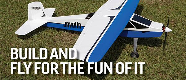
Written by Fitz Walker Old School Model Works Javelin As seen in the October 2020 issue of Model Aviation. Review Bonus Video At A Glance Specifications Flying weight: 5 pounds, 9 ounces Wingspan: 60
Written by Fitz Walker Moustache Model Works 20cc DHC-2 Beaver As seen in the FEBRUARY 2020 issue of Model Aviation. Bonus Video At A Glance Specifications Model type: Semiscale electric/gas Skill


 The full-scale Beechcraft AT-10 began under the designation of the Model 25 and was designed in 1940 to meet the U.S. Army Air Corps (USAAC) requirement for a trainer suitable for training bomber and transport pilots in aircraft with multiengines and retractable landing gear.
The design required the use of nonstrategic materials because of possible shortages of aluminum during the war effort. Model 25 was built primarily of wood and was presented to the USAAC in the same year. The prototype crashed on May 5, 1941.
Beechcraft began redesigning the aircraft the following day, designating it as Model 26. It made its first test-flight on July 26 of the same year. It was delivered to the USAAC under the designation of AT-10, and later named Wichita after Wichita, Kansas, where the airplanes were manufactured. By the end of 1942, 748 AT-10s had been delivered by Beechcraft, and by 1943, a total of 1,771 airplanes had been built. Additionally, 600 AT-10s were built by Globe Aircraft before production ceased in 1944.
The AT-10 had a 44-foot wingspan, an overall length of 34 feet, 4 inches, and a maximum takeoff weight of 6,130 pounds. Two Lycoming R-680-9 air-cooled radial engines, rated at 295 hp each, provided power for a top speed of 198 mph, a range of 770 miles, and a service ceiling of 16,900 feet.
The full-scale Beechcraft AT-10 began under the designation of the Model 25 and was designed in 1940 to meet the U.S. Army Air Corps (USAAC) requirement for a trainer suitable for training bomber and transport pilots in aircraft with multiengines and retractable landing gear.
The design required the use of nonstrategic materials because of possible shortages of aluminum during the war effort. Model 25 was built primarily of wood and was presented to the USAAC in the same year. The prototype crashed on May 5, 1941.
Beechcraft began redesigning the aircraft the following day, designating it as Model 26. It made its first test-flight on July 26 of the same year. It was delivered to the USAAC under the designation of AT-10, and later named Wichita after Wichita, Kansas, where the airplanes were manufactured. By the end of 1942, 748 AT-10s had been delivered by Beechcraft, and by 1943, a total of 1,771 airplanes had been built. Additionally, 600 AT-10s were built by Globe Aircraft before production ceased in 1944.
The AT-10 had a 44-foot wingspan, an overall length of 34 feet, 4 inches, and a maximum takeoff weight of 6,130 pounds. Two Lycoming R-680-9 air-cooled radial engines, rated at 295 hp each, provided power for a top speed of 198 mph, a range of 770 miles, and a service ceiling of 16,900 feet.


Comments
Interesting build
Interesting build
Add new comment