Bend music wire up to 3/16 inch or 5mm with this handy tool
By Jim Ryan [email protected] | Photos by the author
As seen in the May 2023 issue of Model Aviation.
One of the challenges for scratch-building larger model aircraft is accurately bending music wire for landing gear, cabanes, and other components. Commercially available benders tend to fall into two groups: small units that lack the strength for bending heavier wire, and large benders that are expensive and fidgety to use.
To fill this gap, I designed a simple bender that would be cheap to build with basic machine tools (mainly a drill press) and would accurately bend music wire up to 3/16 inch or 5mm. This bender is simple to operate and can be built in a single afternoon. The following pictures will describe the project.
01. The basic materials are an approximate 7-inch square block of 3/4-inch cold-rolled steel (CRS) and a roughly 16-inch length of 3/4-inch round CRS bar stock. These were purchased at a local scrap yard for less than $15.
02. The first task is drilling the holes in the bar stock handle. The author wasn’t happy with the results he got using a V-block, so he cut 2-inch square blocks of medium-density fiberboard (MDF) and bored them, as shown, to support the round bar. The pine fence sets the Y axis for the center hole, and the MDF block sets the X axis. The small piece of 1/4-inch plywood protects the drill press table. Because all of the holes are drilled with the blocks up against the pine fence, their centers will intersect perfectly, and because you’re drilling through the MDF, the drill bit can’t "walk" before penetrating the steel.
03. The pre-bored MDF blocks are slipped over the bar stock handle, with each centered at their respective locations. A spare block is positioned at the edge of the table to support the free end of the bar. Use cutting fluid or light machine oil while drilling steel. For more details on this technique, refer to the author’s article "Precision Machining Without Precision Machines" in the January 2020 issue of Model Aviation, or online at the link in the "Sources" section.
04. The various holes are drilled in the baseplate, again using a drill press and cutting fluid. The author suggests draping an old towel or drop cloth under the drill press table because the oily steel shavings will fly everywhere. Be sure to wear approved eye protection for this and all metal cutting operations.
05. The 5/32-inch holes are tapped for 10-32 National Fine (NF) threads and the 5/16-inch hole for the pivot post is tapped for 3/8-16 National Coarse (NC) threads. Use plenty of cutting fluid and take your time; you don’t want to ruin all of your careful work by snapping a tap inside the hole.
06. The bender components are ready for assembly. The baseplate and handle both have 10-32 threaded holes both 5/8 inch and 1 inch from their pivot holes. The closer holes allow crisper, more precise bends for wire 5/32 inch and smaller, while the farther holes give greater leverage for wire 3/16 inch and larger so that the heads of the cap screws won’t shear off. The locking stud is a plain 3/8-inch bolt with the head cut off and a 3/16-inch or 5mm hole drilled through the shank. The 3/8-inch pivot post should be cut from a heat-treated 3/8-inch socket head cap screw to have the necessary hardness.
07. The bender should be bolted to a secure work surface. Note that the holes for the 1/4-inch cap screws are counterbored so that the heads are recessed below the surface, allowing clear 360° travel for the bender arm. You can even bend coil-spring landing gear struts. The baseplate overhangs the edge of the bench to allow clearance for the locking stud. Because the mounting bolts are only under shear loads, nuts are optional.
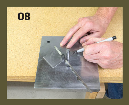
08. Before mounting the music wire in the bender, the correct angle (in this case, 108°) is marked using a machinist’s protractor and a fine-tip Sharpie. This gives you a target to aim for.
09. For duplicate parts, such as landing gear legs, mark the bend locations with a Sharpie to make sure the two pieces match. The locking stud keeps the music wire from creeping during the bending operation, allowing more accurate bend locations.
10. The bending operation should be slow and smooth to avoid overstressing the wire. Because the wire will spring back a little, you’ll need to go slightly past your angle reference mark. For the second bend shown here, a scrap piece of 3/4-inch MDF supports the free end of the wire so that both bends are in the same plane.
11. The completed landing gear strut is ready to remove from the bender. The simplicity, accuracy, and repeatability of this bender is a big improvement over using a bench vise or on another improvised method for bending wire.
12. The two landing gear struts are compared with the template from the plans. They match perfectly, and all that remains is to trim the axles to the correct length.
13. The template seen here can be downloaded at
www.modelaviation.com
Bill of Materials:
(1) Approximately 7-inch square block of 3/4-inch CRS
(1) Approximately 16-inch piece of 3/4-inch CRS bar stock
(1) 3/8 16 × 3-inch socket head cap screw
(1) 3/8 16 × 2-inch bolt and nut
(2) 1/4 20 × 2-1/2-inch socket head cap screws
∗
(2) 10 32 × 3/8-inch socket head cap screws
∗Length depends on thickness of mounting surface.
SOURCES:
"Precision Machining Without Precision Machines" article
Model Aviation, Jaunary 2020
www.ModelAviation.com/precision-without-machines


Comments
Drilling template
The template in figure 13, when I click the link the template is nowhere to be found. Can you post a link to that file please? Thanks!
Bend wire
Ditto the last comment
Add new comment