
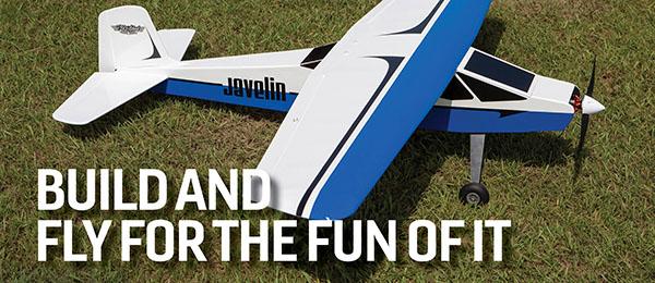
A simplistic FF ruber Design Article, photos, and design by Tom Houle Read the full article in the July 2014 issue of Model Aviation.
Order Plans from AMA Plans Service
Image
Image

Leeon Davis wanted his own airplane, but he didn’t want to spend a large amount of money to achieve his goal. He looked to see what was available, then decided to design his own. Drawing on his professional metal-working experience and skills, Leeon designed an easy-to-build, two-place airplane that only required simple aluminum cutting and bending. The design had to transport two adults and some baggage. Leeon used the Clark Y airfoil to ensure plenty of lift out of the smallish wing. The Davis DA-2A square, boxy outlines could not be easier for the homebuilder. Leeon’s design employs a simple box fuselage. The cockpit section is framed with lightweight, square steel tubing. All of the formers, frames, and other parts are short enough to be bent up on a small brake, and then riveted together. The airplane has constant-chord wings and V-tail, and the side engine cowling cheeks are simple curves. I’ve always admired the simplicity of Leeon’s design and vowed that someday I’d build a FF Scale model. I searched online and turned up a pair of Davis DA-2A peanut plans by Lloyd V. Hunt and William McCombs respectively. These plans were helpful in visualizing the airframe for a larger model. A Google search turned up a number of Davis DA-2A photos. I tracked down a three-view from a 1971 issue of Air Trails magazine. H.G. Frautschy, executive director of the Experimental Aircraft Association’s (EAA) Vintage Aircraft Association, provided me with EAA Archive photos. The full-scale DA-2A photo in this article is courtesy of the EAA Archive. Before I get into the aspects of how I designed and built this interesting airplane, I opted to use old-fashioned rubber for power; however, there are lightweight RC and electric power systems that would fly this airplane. Had I chosen RC electric, I would have left the V-tail feathers fixed and used aileron controls. Let’s get started.
Nose-gear strut, balsa wheels, and carved propeller
I started constructing the Davis with the nose-gear wheel and strut assembly. My goal was to fabricate a nose-gear tire and strut that would closely replicate the one used on the full-scale aircraft. I began by cutting a 3/16 x 21/2-inch strip of brass from a sheet of .010-thick brass. Scissors will do to rough-cut the brass. I smoothed and filed the strip straight and deburred the edges. I cut the strip long to allow for handling and soldering. I spotted a hole in the strip midway between its ends and drilled and reamed it to 3/32-inch diameter. I cut a couple of crosswise slots at one end of a length of 3/32-inch brass tubing. You can determine the length of the tube from the plans. After I flared the tube’s slotted end with long-nose pliers, I slipped the tubing through the brass strip and soldered the tube to the strip. The tube should be square to the brass strip. I carefully formed the brass strip over a 5/16-diameter dowel and then marked the two axle holes, which are shown on the plans. I drilled these holes with a pin vise to clear a .030 brass wire axle. I inserted a 5/16 basswood block between the brass strips while I drilled out the axle holes. Finally, I trimmed the ends of the brass strip, and radiused the ends as shown on the plans. I cut the 3/32-inch brass strut tube to its final length as shown on the plans. The tube will slip over a .045 music wire strut that extends from the bottom of the fuselage cowling. I did not attach the tubing strut to the .045 wire until after I had sheeted the fuselage cowling. CA glue will hold the tubing strut to the .045 wire. The wheel diameters are 11/8 inches for the nose wheel and 11/4 inches for the main gear. I looked through my parts collection and on online, but was unable to find wheels that matched my required diameters. I’d heard of builders who turned their own wheels, but I had never before tried it. I found an article that made it seem so simple I had to try it. All I needed was hard 1/16 balsa sheet, 3/32-inch brass tubing, and a Dremel or similar power tool. A small drill press would also work. The three wheels are cross-grain, laminated, hard 1/16 balsa. Laminate enough balsa sheet to make three wheels and then some. There will likely be a gentle learning curve. The main gear wheels are 11/4 inch in diameter and require seven 1/16 cross-grain laminations. The nose wheel is 11/8-inch diameter and requires four cross-grain laminations of 1/16 balsa sheet. I used CA glue to laminate my wheel stock. After the glue had kicked, I laid out the wheel circles and their centers. I laid out a few extra wheels just in case I botched my first attempt. I cut the circles from the laminated balsa approximately 1/16 inch too large. I drilled holes through the wheel centers to clear lengths of 3/32-inch diameter brass tubing. I cut the brass tubes a couple of inches long. Before I glued the brass tubes to the rough-cut wheels, I checked each tube to make sure it was perfectly square to the face of each wheel.Image

Cut and form a .015 inch brass sheet. Slot and flare the end of a piece of 3/32 diameter brass tubing. See plans for the tubing length and forming the brass sheet.
Image

Solder the flared end of the 3/32 tubing to the .015 brass sheet.
When satisfied, I soaked the point where the tubing goes into the balsa wheel. The CA glue will wick deeply into the balsa and retain the tubing. The tubing extension functions as the axle bearing, providing a mandrel to chuck into my Dremel hand tool. I initially ran my Dremel tool at a low speed to check for wheel wobble. If there is any wheel wobble, make a new wheel and extended axle. To shape my wheels, I held the Dremel tool in one hand and a folded piece of 80-grit sandpaper in the other. I set the Dremel tool to a low speed until I determined how the balsa would react to the sandpaper. As I gained confidence, and each of the wheels approached its final outline and cross-section, I turned up the speed and lightly applied the sandpaper to the wheels. A final smoothing with 150-grit sandpaper will polish the balsa. If there are any dimples in the balsa tires, you can easily fill them with Squadron white or green putty. After the wheels were turned, I cut off the brass tubing extensions with a Zona saw. I was amazed by my first attempt at making wheels. It is easy to do; just remember to keep a light touch with the sandpaper. The entire process only took an hour or two to complete. The 7-inch propeller dimensions came from an article on propeller carving by Bill Henn, which I found online. The propeller block layout is shown on the plans. I carved mine from hard balsa and attached a rough-shaped balsa spinner to the hub, which I final sanded after I had attached it to the propeller. With the parts finished, I turned my attention to constructing a simple pair of wings.
Wing Construction
The wings are an easy-to-build, one-piece affair. They may not look strong enough, but my rough-and-tumble initial trimming flights proved they could withstand ground contact. I cut a rib template from Styrene, then, traced the rib outlines onto 1/16 balsa sheet. I cut the 3/32 x 1/4 -inch TE from hard balsa. I shaped and sanded the correct angular cross-section into the strip. The LE is hard 1/8-square balsa. The wing spar is a 1/16 square balsa and corner and dihedral gussets are 1/16 balsa sheet. I built my two wing panels and the center section directly over the plans. I pinned down the wing center section, blocked up the wingtips to 15/8 inches at each tip, and glued everything together, adding 1/16 balsa sheet gussets at the dihedral breaks and corners. At the point, I shaped and sanded the LE. The ribs with notches in their undersides accept the 1/32 aircraft plywood rectangle that holds the main landing gear .045 wire. I bent up the main gear to the true length shown on the plans, and then using soft brass wire, I sewed it to a 3/8 x 31/2-inch length of 1/32 aircraft plywood. I added the 1/32 balsa sheet wingtips to complete the wings and ready them for covering. I covered my wings with from Easy Built Models domestic white tissue.Image

Construction of the wings could not be simpler. Strong and light, it will hold up to first flights. The tip ribs are covered with 1/32 soft sheet.
Image

Note the center section ribs are notched to accept the 1/32 aircraft plywood main gear leg mounting plate. The .045 music wire struts are bound to the plywood with 28-gauge soft brass wire. CA glue secures everything.
Tail Feathers
Building the V-tail feathers was easy. I used 3/32 square strips throughout for a strong, warp-free structure. I cut the corner gussets from 3/32 balsa sheet. Use the plans to ensure the correct dihedral for the V. After gluing the two halves to the correct dihedral, I covered my tail feathers with Easy Built Models domestic white tissue. To prevent warps when I shrank the tissue, I blocked up and pinned down the V-tail surfaces and shrank the tissue in two steps. When the tissue was taut, I added a 3/32 balsa sheet angle brace to the V-tail LE. The angle brace pattern is shown on the plans. I sheeted in the valley with 1/32 balsa sheet from the 3/32 angle brace from the LE to the TE. I set aside the finished tail feathers and moved to the fuselage.Image

Unassembled V-tail plates, super simple 3/32 square construction. Be sure to pin it down when the tissue is shrunk.
Image

The assembled V-tail. Do not assemble until after the two halves are covered with tissue. Note the 3/32 sheet angle attached to the leading edge of the V-tail. The balsa angle ensures a correct V dihedral angle.
Fuselage Construction
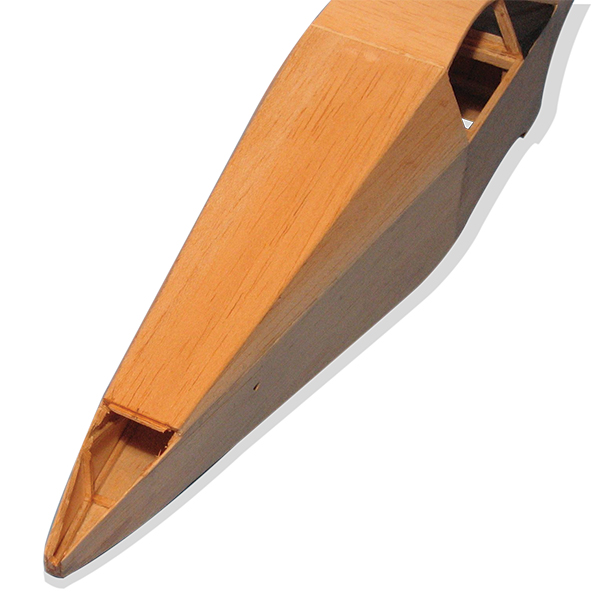
I began constructing the fuselage, cutting and gluing formers A through E. Formers B through E are soft 3/32 x 3/16 balsa square strips. Former A is 1/32 aircraft plywood laminated to a 3/32 balsa sheet. I cut the wing saddles from soft 3/32 balsa sheet. You will need to cut the saddles before you begin the fuselage assembly. The basic fuselage structure consists of two 3/32 square sides and the 3/32 wing saddles. To ensure identical sides, they were constructed one on top of the other directly over the plans. I made up a pair of curved upper cockpit bows from two strips of 1/32 x 3/32 basswood. I soaked the basswood in hot water, then laminated and molded the bows over a pair of balsa forms. After the bows had dried, I spliced them to 3/32 square upper longerons. These longerons run from the top rear of the cockpit sides to the aft end of the fuselage. Before I erected the two 3/32-inch sides over the plan view, I notched the upper and lower longerons to accommodate angular breaks in the fuselage sides, then pinned formers B through E upside down over the plan view. Note that the canted upper halves of formers C to E are not yet attached. They are installed after the basic fuselage is removed from the plans. Make sure formers B through E are vertical to the building board and that they align with the fuselage side uprights. At this point, I added the 3/32 upper and lower crossmembers at the nose (former A) and the aft fuselage break point. When I pulled together the nose and tail posts, I made sure the sides were centered over the plan view. Next, I installed the rear peg uprights, which are 1/32 aircraft plywood sheet laminated to 1/16 sheet balsa. After removing the basic fuselage assembly from the plans, I attached the three upper fuselage canted formers C through E. I attached former A to the front of the fuselage. The .045 music wire nose strut was next. Using the side view as a guide, I bent up the .045 music strut, and then bound it to a piece of 1/32 aircraft plywood with soft brass wire. I glued the plywood into the bottom face of the nose, notching the plywood into the bottom of former B so the wire and plywood would not interfere with the 1/32 balsa sheeting yet to be added. The wire and plywood enable a solid nose-strut attachment and add needed nose weight. The soldered brass tube nose strut slips over the .045 music-wire extension. CA glue holds the brass in place. Align your telescoped nose strut fore and aft before you CA glue the brass tubing to the music wire. At this juncture, I attached the curved upper cockpit bows at their respective notches in upper formers C through E. The attached turtledeck longerons run to the rear of the fuselage and are faired into the upper fuselage longerons at the LE of the V tail. Now I was ready to begin sheeting the fuselage. Because the side cheek cowls are the trickiest part of the sheeting, I started there. First, I added 1/32 balsa sheet to the flat top and bottom faces of the cowl from former A to former B. I cut a slot in the lower sheeting to allow the sheeting to fit around the nose strut. I filled in the slot with scrap balsa. I rough-cut the curved cheek sheeting from soft 1/32 balsa sheet, then soaked the pieces in hot water. I wrapped the balsa around the curved sides from formers A to B, and held the pieces in place with my fingers and masking tape while I spot glued the curved sheeting to the fuselage with CA glue. These are simple curves. As long as the balsa is soft and well soaked, it’s an easy wrapping process. The wet balsa will not affect the adhesion of the CA glue; water may actually cause the glue to kick even quicker. With the nose cowling sheeted in, I worked my way aft starting at the bottom of the fuselage, then the lower sides, upper sides, and finally the top of the turtledeck. The entire fuselage is skinned with soft 1/32 balsa sheet. To add strength to the cockpit and facilitate sheeting the curved cockpit bows, I ran that sheeting cross-grain. I then framed in a 1/2-inch opening at the rear peg to assist in installing the rubber motor. I block sanded the sheeted fuselage, using Squadron white putty to fill dings in the soft balsa. I built the nose block from seven cross-grain laminations of 1/16 balsa sheet. I shaped it as shown on the side and plan views. The nose plug is three cross-grain laminations of 1/16 balsa sheet. The nose plug must fit tightly into the square diamond opening in former A. I did not build down or right thrust into the nose block. Down thrust is included in the angle of former A. For flying purposes, it was about all the down thrust I needed. I used an old Jasco ball-bearing thrust washer on my propeller. I slipped it onto the propeller shaft before I bent the rubber hook into the .045 music wire.Image

The finished nose strut with .030 brass wire axle. Solder the axle ends after the nose wheel is in place. Tubing slips over .045 music wire strut. CA holds the tubing to the strut.
Image

Laminated balsa wheel turned on a Dremel tool. The 3/32 diameter brass tubing is cut off after turning the wheel. Paint flat black. Add silver paper or Styrene hub disks.
Image

The propeller should be hard balsa, pine, or basswood. Note the slightly rounded blade tips. Start sanding with 50-grit sandpaper and work up to 220-grit. The finished propeller gets a couple of coats of clear dope, then painted silver with a red spinner. Propeller shaft is .045 music wire. Thread is bound and CA glued to the propeller hub. A Crockett or other hook is required for winding.
Image

The two fuselage sides, 3/32 square and 3/32 sheet wing saddles. To ensure sides are identical, build one side atop the other.
Image

Fuselage formers B through E are constructed over the plans. Use 3/32 x 3/16 balsa strips. Install the top halves of formers B to E after the fuselage sides are erected. The cockpit bows are laminated 1/32 x 3/32 basswood strips. Angle splice the bows to 3/32 square. balsa turtle deck longerons.
Image

The assembled fuselage is ready for former A and the tops of formers B through E.
Image

Former A and the tops of formers B through E attached to the fuselage. The laminated cockpit bows are attached next.
Image

The brass tubing nose strut assembly ready to slip over the .045 music wire extension. The 3/32 sheet backing at former A facilitates gluing the 1/32 sheeting to the cowl cheeks.
Image

Retain the brass nose strut tubing with gap-filling CA glue.
Image

The cockpit bows and turtle deck stringers installed. Note the turtle deck stringers run to the L. E. of the V-tail assembly.
Image

Fuselage sides and bottom sheeted with soft 1/32 balsa sheet. The 1/32 cockpit top sheeting runs cross-grain.
Image

The nose strut radiator housing is built up from soft 1/16 balsa sheet. Note the opening at the bottom rear of the fuselage for attaching the rubber to the rear peg.
Image

The fuselage sheeting completed. The three windshield supports are 3/32 strip. The instrument panel glare shield is black construction paper.
There is a built-up box under the nose cowling where the nose strut exits. I believe this is a radiator housing. Note: the fairing on the bottom of the nose block aligns with the front face of the radiator housing. I built my radiator housing per the plans with soft 1/16 balsa sheet. In retrospect, because I had to add nose weight, I could have used heavier balsa or even plywood. I slotted the housing to accommodate the nose-gear strut. An instrument shroud on the full-scale aircraft runs from the top edge of the panel to the front edge of the windshield. I replicated this detail with folded black construction paper. At this point, I added the windshield center and corner 3/32 balsa supports. I also added paper hubs painted silver to the three balsa wheels. Except for paint and trim, this completes the fuselage.
Covering, Assembly, and Painting
I covered the wings and V-tail components with Easy Built Models domestic white tissue. I also I added washout to the wingtips. I used Elmer’s white glue to attach the wings to the fuselage wing saddles. The glue gave me some time to accurately position the wings before it cured. Fitting the V-tail into the rear of the fuselage took some adjusting. I had to angle the inside faces of the upper fuselage longerons to enable the V-tail assembly to fit snugly into the fuselage with the LE of the V-tail set at zero incidence. I left the rear of the V-tail loose to allow glide trim adjustments. I gave the model a light spray coat of Krylon Matte spray, then a light coat of Design Master floral spray. This lightweight spray is available in many colors at craft stores. I did the aileron and elevator markings with a black Sharpie pen. The wing walk is black tissue. The front of the nose block is painted flat black to simulate the open cowling behind the propeller hub and spinner.Image
Bevel trim the inside faces of the fuselage top longerons so that the V-tail assembly rests on the top edges of the top longerons.
Image

The top edge of the 3/32 angle gusset at the LE of the V-tail assembly should sit exactly 1/32 below the top of the turtle deck sheeting. This positions the LE of the V-tail assembly at 0° incidence. Fill the space between the V-tails with a triangular piece of 1/32 sheet. Leave the TE of the V-tail assembly loose to allow shimming in negative incidence.
Image

The finished model was sprayed with yellow floral paint over the tissue.
Flying Notes
I added some nose weight to balance the airplane at the point shown on the plans. I made the test glides without rubber over tall grass at a park near my home. The Davis is no lightweight. It doesn’t glide well, but I was able to get reasonably flat test glides with nose weight and a 1/32 shim beneath the TE of the V-tail. I began powered flights with six strands of braided FAI TAN super sport rubber. It wasn’t enough to gain much altitude, but eight strands did the trick. The model climbs out quickly in an open, left-hand circle. I suggest keeping that turn open with a slight amount of right thrust. It’s definitely not an endurance model, but it sure is pretty in the air.Image


Comments
Davis DA-2A
Came out very pretty, but built for... Hurricane 🌀 chasing?! 😂
Personally, I would have left off all that planking, covered it in light, colored tissue, and given that very light clear coats to seal the tissue.
I built the peanut decades ago, and it was a good flyer as I recall, in white Japanese tissue.
Dave - Colorado
Add new comment