Imagine launching a model off of a hill, over a sloping alpine meadow into lift that pushes the aircraft higher and higher …
By Bob Sifleet
Photos by the author except as noted
As seen in the May 2006 issue of Model Aviation
The ideal flying sites for Free Flight (FF) modelers are large, flat fields of grass that are unobstructed so that long flights can be made without going behind or into obstructions. Motorbikes are a necessity for FFers; they are used to retrieve the aircraft.
What type of FF models can be flown in mountainous regions where the terrain limits normal FF activity? An event has evolved in Europe that makes use of hilly terrain for competition. Imagine launching a model off of a hill, over a sloping alpine meadow into lift that pushes the aircraft higher and higher as it glides into the wind and down a slope for a five-minute maximum flight.
Peter Brooks launches his F1E entry into a group of models that are climbing away in a standing wave. Croghan photo.
The Class: For more than 50 years modelers in the mountainous regions of Central Europe have been flying FAI class F1E for FF Slope Soaring Gliders. The models are flown from a hill or slope and glide in a relatively straight line into the wind.
An automatic steering device keeps the aircraft directed into the wind. It consists of a forward fin with a rudder that is attached with an adjustable coupling to a magnet that steers the model in the desired direction.
If the glider veers to the left, the magnet moves the rudder to the left, which forces its nose to the right. If the glider turns right, the rudder will turn right and the model will turn to the left until it is again heading in the desired direction.
The rules for class F1E allow for a wide range of model sizes and design ingenuity. The maximum surface area is 150 dm2 and the maximum wing loading is 100 grams per dm2. The maximum flying weight is 5 kilograms. A contestant may use as many as five models in any contest.
A contest normally consists of five one-hour rounds. The rounds usually start at 10 a.m. or later to have a breeze present. The maximum flight of three to five minutes is determined by the wind velocity or flying-site conditions.
Flight scoring differs from the total accumulated flight times used for duration-type FF competitions. Each flight is scored by dividing the flight time by the max time and then multiplying by 100.
If the max is 300 seconds and a flight is 150 seconds, the score is 150/300 = .5 x 100 = a score of 50. This method of scoring allows changing max flight times without affecting the final scores, which occurs in other FF events when max times are changed.
A flyoff is held if two or more competitors have scored 500 points or have identical scores at the end of five rounds. The flightline is usually moved down the slope to make the max more difficult to achieve. The first flyoff is normally seven minutes. For successive flyoff flights, the flightline is moved farther down the slope and two minutes is added to the previous max time.
The Models: F1E Gliders usually have medium-aspect-ratio wings and a generous stabilizer area. The wings and stabilizers are made with the state-of-the-art carbon D-box with carbon/balsa spars, carbon-fiber TEs, and rib caps. Four-piece wings are almost universally used, to allow the models to be transported easily and, more important, to make the wings less susceptible to damage from hard landings.
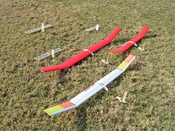
Sizes of F1E models. Bottom: midsize, for average conditions. Top left: large, for calm and light wind. Top right: Small, for strong winds.
The wingtips are held on by a small-diameter wire that fits into tubing in the spars. This wire is bent to provide tip dihedral. A small piece of tape is put around the TE to hold the tip in alignment. The main wing panels are held together by a large carbon or wire joiner.
Kevlar/carbon-fiber composite tubes are normally used for the entire fuselage. The long tailboom and front end are detachable behind the wing. This also makes it easier to transport the models in compact model boxes. Clockwork and occasionally electronic timers are used for dethermalization and for various stabilizer functions including bunt.
The nose pod is usually a teardrop-shaped unit that contains the steering mechanism, commonly called the “pilot.” A jewel bearing is located in the bottom center of the nose pod.
The forward fin is attached to a keyed flat plate that is affixed to the top of the nose pod with rubber bands. This allows the forward fin, steering fin, and magnet to be detached during a hard landing to avoid damage.
The hinged rudder is attached to the forward fin, and the magnet housing is attached to the lower part of the rudder. A ball bearing or pointed shaft is located on the lower end of the magnet housing and rests on the bearing.
The rudder can be adjusted to be straight with the forward fin, with the model oriented in any direction. When the glider changes flight direction left or right, the steering rudder being turned by the magnet will move in the opposite direction. This allows the steering to move the model back to the intended orientation.
Flight: F1E gliders are sent aloft by hand-launching them from a hill; however, some modelers have perfected a bunt-type launch. The models are launched at a 30°-40° angle with as hard a push as possible with the stabilizer set at a ballistic cruise angle, and bunt function occurs in 1.2-1.5 seconds. A good bunt launch can result in 15 feet of additional altitude that will start the flight high enough to be out of ground turbulence and in a stronger part of the standing wave.
Tom Ioerger checks in with the timers. Nosko photo.
The glide is adjusted to be somewhat faster than other FF models’ slow maximum performance glides. This trim will prevent stalling and instability that can result in the model’s turning rapidly in turbulence. The aircraft must penetrate the wind slowly with good stability.
Ballast can be attached to the model to increase the glide speed, which helps the aircraft penetrate stronger winds. This precludes having the model drift downwind into or over the hill. A log of wind speeds vs. ballast required for each model is helpful to determine how much ballast to use at a particular wind velocity.
In addition to ballast, a fast-glide function is used on models that are designed for strong wind conditions. These aircraft are adjusted for fast, penetrating flight to allow them to glide away from the slope upwind from the launch position to get away from wind currents that would carry them backward over the top of the hill.
Models hang nearly stationary overhead in a strong breeze. Nosko photo.
When the model is far enough upwind and down the slope, the stabilizer is activated by the timer to a normal glide setting that allows the model to climb high in the standing wave.
One might assume that each slope where F1E is flown has unique lift conditions that vary with wind direction and velocity. It is necessary to make many practice flights to learn a particular flying site’s characteristics.
F1E gliders are not always flown directly into the wind. Occasionally it is necessary to fly crosswind to keep the model in lift. Flying parallel to a hill or ridge at an angle to the wind can be achieved by adjusting the pilot to steer at an angle to the wind, much like a tack angle with a sailboat.
Vince Croghan watches his model float overhead shortly after launch during a practice session. Croghan photo.
To avoid landing in rough terrain such as trees, buildings, etc. at the bottom of the slope, a circling option can be incorporated into the models. The steering rudder is furled to one side by a timer-activated device to make the aircraft circle and drift back toward the launch location, thereby avoiding landing at the bottom of the slope. Since both wings are set with no angular difference between them, a small amount of up-elevator must be put into the stabilizer when the circling begins to avoid spinning in.
The Competitors: F1E is extremely popular in Europe. Romania, Hungary, Czech Republic, Slovakia, Germany, Poland, Switzerland, and Austria make up the hotbed of F1E competition. Forty or more pilots often participate in F1E competitions. This number rivals or exceeds the number of pilots who flies in any of the other F1 FF classes. There are usually 17 World Cup contests and many local competitions in the seven countries where F1E is most popular.
F1E was not flown in the US until 2000, when John Davis started working with the event. He placed fourth at the 2001 World Championships and started a program to encourage others to fly F1E.
In 2003 I won the World Championships, which was held in Romania. At the 2005 World Championships in Slovakia, Vince Croghan placed third and the US team finished in second place.
2005 F1E World Championships contestants await a favorable breeze at the scenic flying site at Liptovsky Mikulas, Slovakia. L-R: Bob Sifleet, Manfred Rennecke of Germany, Vince Croghan. Croghan photo.
Resources: Anyone who enjoys flying FF models would probably find flying F1E Gliders challenging and enjoyable. The aircraft are inexpensive in comparison to F1A, B, or C models. The only support equipment required is a good pair of hiking boots to climb back up the slope after a long flight.
The 2004 National Free Flight Society (NFFS) Symposium contains an excellent presentation on the construction of F1E magnetic-steered gliders. Daniel Petcu of Romania is the author. In the same issue, Marian Popescu, also of Romania, was awarded the Model of the Year for his F1E Marpo. Tom Ioerger, Vince Croghan, and I used this design at the 2005 F1E World Championships in Slovakia.
Autopilot Breakdown
Components: nose pod with bearing in center, magnet assembly with small ball at the lower end to fit in 3 bearing, forward fin, steering fin.
Magnet and fin assembly.
Complete autopilot.
Close-up of assembly. Screw at bottom of rudder locks magnet to steering rudder after it is set for proper direction orientation.
Top view. Steering rudder is to left. This will push model’s nose to right until steering rudder is straight.
SOURCES:


Comments
FAIF1E
Very interesting story about a niche model airplane competition not very well served in this country(US).
Add new comment