
A rarely modeled 1925 biplane design

The Alexander Aircraft Co. was founded in Colorado in 1925 as an offshoot of the Alexander Film Company. Founder Don Alexander thought that the company could sell more advertising if it had airplanes. After contacting several aircraft manufacturers requesting a quote for 50 airplanes and was ignored, he decided that he would build his own. The operation moved to Englewood, Colorado, where Don set up his company.
It began when Justin Mclnaney was sent to Marshal, Missouri, to buy an airplane and learn to fly under the tutelage of his instructor, Ben Howard. Justin purchased a Swallow and, despite a number of forced landings, flew it back to Denver, where he became an instructor and taught several new pilots to fly, including Jack Frye, who later became president of Trans World Airlines, and future airplane designer, Al Mooney. The company reached sales of as many as eight aircraft a day shortly before the Great Depression hit.


PURCHASE PLANS HERE or
DOWNLOAD FREE PLANS!
TILED PLANS
FULL PLANS


In late 1928, a fire broke out in the fabric shed where wings were being coated with nitrate dope. The shed was fully engulfed, and because there was no escape route, several employees were killed or severely injured. Company officials were charged with involuntary manslaughter, to which they plead guilty, were fined $1,000, and given suspended 90-day jail sentences. The company went bankrupt in 1932 and was purchased by Aircraft Mechanics Inc., which produced components for the Douglas Aircraft Co. during World War II, U.S. Air Force ejection seats, and crew seats for the space shuttle program.
In 1928 and 1929, Alexander was the largest aircraft manufacturer in the world. In the 1930s, the company produced the Bullet, a low-wing monoplane with retractable landing gear. The Bullet was eventually certified and became famous in racing and civilian aviation; however, because of the Depression and losses from the Bullet program, the company folded.
The Alexander Eaglerock was a two-seat biplane that was introduced in 1925 and powered by a Curtiss OX-5 engine. In all, 893 Eaglerocks were built. The Eaglerock had a top wingspan of 36 feet, 8 inches; an overall length of 25 feet, 11 inches; a gross weight of roughly 2,400 pounds; and a range in excess of 500 miles with a cruise speed of 90 mph.
The Model
The model was designed with a 50.6-inch wingspan at 1:8.7 scale. Although it is relatively large, its light wing loading makes the model an ideal candidate for small parks, but it is big enough to fly at larger RC fields as well.
Construction is primarily of balsa and light plywood. It features removable wings for transport in smaller vehicles. Power is provided by an economical 450- to 480-class outrunner motor with a 2S LiPo battery. Construction is of the typical stick-frame-style balsa structure with the eggcrate-style of wing construction. Bowed outlines are incorporated into the flying surfaces to create a lightweight, yet strong, airframe.


Building the Eaglerock
Begin by cutting out all of the parts from the appropriate sizes of sheet balsa using the provided cutting patterns. If laser-cut parts are your preference, a short kit, containing the laser-cut wood and vacuum-formed plastic parts, is available from Manzano Laser Works.
With parts in hand, it is best to build the subassemblies first so that those components will be ready when they’re needed. The wingtips, rudder, and elevator tip outlines are laminated from balsa over artist foam board using the provided patterns. The landing gear components are bent from 1/16-inch diameter wire using the bending patterns and assembled on a jig made from scrap wood.
The cabane struts are prebent at the bottom only and marked A, B, and C as shown. The top bends will be made later. The radiator is made from either scrap balsa or from balsa or blue foam blocks. The inlet screen can be made from an old mesh teabag or fine brass screen, and the front is bordered with 1/16 × 1/8-inch balsa.
The cabane mounts are laminated together, the interplane struts assembled, and the 1/16 × 1/8-inch balsa crosspieces are glued in place on the formers, followed by the R4A doublers on the R4 ribs. Finally, former 1/1A and the motor mount assembly are built up, but don’t glue the mount to former 1 yet.
Fuselage Assembly
Build the side frames directly over the plans using the part numbers and wood sizes shown. Make the main landing gear beams using the provided detail drawings and pin them in place on the bottom view assembly drawing. Dry-fit the side frames on former 1/1A and pin them in place over the landing gear beams, and then glued in place. Align and glue formers 2 through 4 in place, followed by the front cabane mount and the two 1/8-inch square bottom crosspieces.
Pull the tail post together and glue. Fit and glue B3 and the remaining top formers and bottom crosspieces in place. Remove the frame from the board and glue the motor mount assembly in place, followed by B4 and CF. Fit and glue all of the top 1/16 × 1/8-inch balsa stringers in place.
Mount the landing gear on the beams and lash it in place with heavy-duty nylon thread. Secure the lashings with thin CA glue. Mount the motor on MM and connect the ESC so that the motor runs in the proper direction of rotation. Feed the ESC through the slot in 1A then add the 1/16 × 1/8-inch balsa bottom stringers.
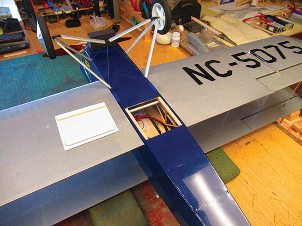
Cut the fuselage fairings from file folder paper using the provided patterns. Glue the fairings in place beginning with the sides, followed by the bottom front. The top is then added starting at the rear and working forward. Align and glue TF in place on center then glue the paper fairing in place.
When completed, fit and glue the wing receiver tubes in place then sand the fuselage assembly to final shape. Locate the holes for the cabane struts and pierce the paper fairings at each of the four locations. Finally, align and glue the battery tray in place.
Rudder Assembly
The rudder assembly is built directly over the plans using the wood sizes shown. Cut the spars to length and pin them in place on top of the plans. Shim the bowed outline with 1/16-inch scrap balsa and pin in place. Fit and glue the ribs in place, followed by the basswood diagonal bracing. Remove the assembly from the board and sand it to shape. Fit and glue the control horn and balsa doubler in place then cut in and dry-fit the hinges at the locations shown.
Horizontal Stabilizer
Cut the hinge spars from 1/8 × 3/8-inch balsa. Slot the elevator spar in the center and glue the toothpick reinforcement in place. Build the basic stabilizer and elevator assemblies directly over the plans using the wood sizes shown. Scrap balsa shims are used to center the leading edge (LE), trailing edge (TE), and tip bows in place. When completed, remove the assembly from the board and sand to the airfoil shape shown. Fit and glue the control horns in place, followed by the four ECH1s glued in flush with the top and bottom surfaces.
Top Wing Assembly
Locate the parts needed to build the top wing assembly. Begin by dry-fitting ribs R1 through R5 in place on A1 and A2 and pin them in place over the plans. Once aligned and pinned in place, glue the points of contact. Align the 1/4 × 3/8-inch LEs and 3/32 × 1/4-inch balsa TEs and glue them in place. Align and glue the laminated tip bow in place; the front of the bow should be flush with the top of the LE.
Fit and glue A6 and A7 in place flush with the bottom of the wing. Align and glue the 32 FR false ribs in place, followed by the 3/16-inch OD aluminum receiver tubes. Finally, align and glue the 1/16-sq. in. basswood diagonal bracing in place. With assembly completed, remove the wing from the board, sand it to shape, then repeat the process to build the other top wing half.


Bottom Wing Assembly
Locate the parts needed to build the bottom wing assembly. Begin by dry-fitting ribs R1 through R5 in place on A3 and A4 and pin them in place over the plans. When aligned and pinned in place, glue the points of contact.
Align the 1/4 × 3/8-inch LEs and 3/32 × 1/4-inch balsa TEs and glue in place. Align and glue the laminated tip bow in place; the front of the bow should be flush with the top of the LE.
Glue ASM in place flush with the bottom of R5SM, followed by ASM1. Align A6 and A7 and glue them in place flush with the top edge of the ribs and spars, followed by the 26 FS false ribs and basswood diagonal bracing. With assembly completed, remove the wing from the board and sand it to shape. With that done, fit and glue the 3/16-inch OD brass joiner tubes in place. Repeat the process to build the other bottom wing half.
Now that all four panels are assembled and shaped, fit and glue all of the 1/4-inch square hard balsa rigging blocks in place and drill the .028-inch diameter holes as shown. Sand the assembly flush with the top and bottom of the wings. Finally, fit and glue the file folder sheeting in place, as shown on the bottom wing, on the top side only.
Mounting the Servos
With the output arms in the neutral position, the aileron servos are glued in place on ASM using silicone caulk. When they are dry, connect the extension leads and bring them out through the root ribs.
Set up the rudder and elevator servo mounts in the fuselage using the wood sizes shown. Mount the servos as close together as possible, centered on the mount beams. Dry-fit the rudder and elevator assemblies in place then, using the continuous rudder cable routing diagram, run in the rudder cables, tie them off at the control horn, and mark on the plans the exact location where they exit the fuselage.
The elevator cables are a continuous loop at each end of the servo arm for both up and down cables. Secure them at the servo arm with a 1/8-inch crimp cut from 1/16-inch OD aluminum tubing. Run the cables through the fuselage, tie them off at the control horns, and mark the exact location where they exit the fuselage. That information will come in really handy after the fuselage is covered.
Covering the Eaglerock
The model can be covered with any of the lightweight iron-on covering materials, such as UltraCote ParkLite or a similar material. It’s also a terrific candidate for lightweight silkspan or even Polyspan and dope. Before the covering is applied, fine-sand the assembly to remove any irregularities in the frames. For best results, follow the manufacturer’s recommendations for the covering material used.


Setting Up the Cabane Struts
Laminate a CJRa on each side of CJR. Slip the cabane struts into each of their respective locations in the fuselage, make the top bends, then dry-fit CJR/CJRa onto the struts. Slot the top fuselage fairing to clear strut A, as shown in the fuselage side view and former 2 detail plans drawing.
To set up the incidence, slip the bottom wing onto the fuselage and set CJR/CJRa to 1° positive, with the bottom wing at 0°. The incidence is measured along the flat bottom of the airfoil. Slip the top wing halves onto the joiner tubes and dry-fit the interplane struts in place. With the top and bottom wing LEs parallel and the top wing at 1° positive, tack-glue the cabanes into the CJR assembly then remove the wings and secure the cabanes in place with 5-minute epoxy.
Final Assembly
Cut the nose bowl to shape and glue it in place using silicone caulk then fit and glue the hinges in place. Plug the bottom wing into the fuselage and align the tail section in place using the wing for alignment reference.
Using the locations recorded for the cable exit points in the fuselage, pull the six control cables through the fuselage. Secure the cables to the control horns using crimps made from 1/8-inch sections of 1/16-inch OD aluminum tube. Connect the ailerons using pushrods made from .032-inch diameter steel wire with a Z-bend at both ends.
Make up the headrest from a balsa or blue foam block and glue it in place. Cut the four 1/8-inch dowel radiator supports 1/4 inch long and glue them in place in B4, with 1/8 inch protruding.
Glue the radiator in place. Fit and glue the 1/6-inch steel wire landing gear braces in place at the rear struts and solder them at the front. Fit and glue the tailskid in place, followed by the main wheels and tail skid, then add the windshields, cockpit combing, and any other desired details.
Rigging the Wings and Tail
Fit the wings in place, followed by the interplane struts. With the wings properly aligned, glue the interplane struts in place and secure the wings with either colored vinyl or clear hinge tape. Build the aileron links according to the detail plans drawing and fit them in place. With the ailerons in the neutral position, connect the links with heat-shrink tubing.
Add the rigging using four pieces of nylon thread for each side. Glue the thread into the holes in the interplane struts then feed the thread through the holes in the rigging blocks. Pull it taut and secure it with thin CA glue. Fabricate the javelins from .080-inch diameter styrene rod and glue them in place where the flying and landing wires cross.
Set up the radio with the control throws as shown on the plans. Set the center of gravity (CG) 2-3/4 inches from the LE of the top wing using the battery to your best advantage then fabricate the battery hatch cover according to the detail drawing provided.


Flying the Eaglerock
Before the maiden flight, double check the CG and propeller rotation, and make sure that the flight controls are working smoothly and moving in the right direction. With a fresh battery installed, you’re ready to go.
The rudder is effective, so ground handling during takeoff is smooth and positive. After it is in the air, the controls prove to be somewhat docile, although the ailerons do exhibit a fair amount of adverse yaw. This is common on a four-aileron biplane.
After the first flights, I set up a 50% differential throw in the ailerons, but a bit of rudder input entering the turns still didn’t hurt. Trim the model for straight-and-level flight at roughly 2/3 power. The stall proved to be abrupt, but it recovered nicely.
The landing approach requires carrying a little power because of the typical "40-mph built-in headwind" that biplanes are known for, but once it was in ground effect, the model floated above the runway and wouldn’t come down until power was reduced more, so plan on flying it all the way to the ground.
All things considered, if you like "old biplanes" as much as I do, this one is a jewel and will no doubt see a lot of air time, as well as a whole bunch of touchand-gos.


SOURCES:
Manzano Laser Works
Hanger 9
HobbyWing Direct


Comments
Add new comment