
Part 3: Completion and flight
Welcome to the third and final installment of the Infield Engineering P-40C build! Last month, we finished the wing, the main gear, and the main gear doors. This month, we’ll complete the construction, get the paint and details on, and get some flights in.
As mentioned in the November 2024 article, this build is an offshoot of the P-36/Hawk 75 from the 2018 "Fighter Face-Off" article in Model Aviation. Like last month, I’ll focus more heavily on describing things that are new rather than repeating things in detail that are available in the earlier build articles.
At a Glance
Specifications
Wingspan: 60 inches
Length: 50.4 inches
Wing area: 591 sq. in.
Flying weight: 79 ounces
Power: 4258-650 Kv motor; 4S 3,800 mAh LiPo battery; 14 × 8 three-blade propeller
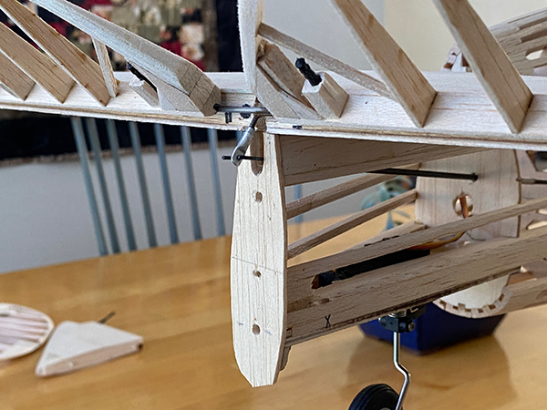
Tailwheel Installation and Steering Control
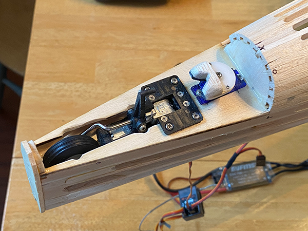
Because the P-40 has a much longer nose than the P-36, I’ve been less concerned about tail weight on this build. With that in mind, rather than using a pull-pull system to steer the tailwheel, this P-40 has a servo in the tail that directly drives the tailwheel. This is a much simpler solution than the pull-pull system. The direct drive only requires a servo with a drive wheel and a contoured fork made from scrap wood.
This kit, as designed, will accept the tailwheel retract from the FMS Model 55-inch P-40. Several of the FMS P-51s use a similar retract unit. After I installed the retract, the correct location for a 5-gram servo was marked on the tailwheel plate (part TP). After cutting a hole, the servo was screwed into position.
A plywood fork was fastened to the top of the wheel on top of the servo. This would be good enough to drive the tailwheel, but it would jam if the rudder and tailwheel were deflected when the tailwheel was descending to the lowered position. The solution was to add a contoured bit of wood to the plywood horn to steer the tailwheel tiller into the fork as the tailwheel tiller dropped toward the slot.
Tail Group Controls
The easiest way to operate the elevators and rudder would be to use a standard pushrod linkage attached to exposed control horns. There’s nothing wrong with that, but for this P-40, my goal was to have no visible control rods on any of the control surfaces.
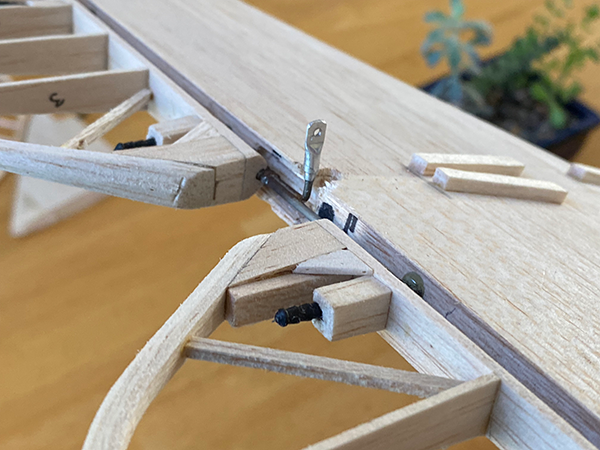
I cheated a little on the rudder. The full-scale P-40 used a pull-pull actuation on the rudder that was exposed, but it was more subtle than mine. My control horns needed to stick out a little farther than scale in order to provide the leverage that my servo needed. In principle, however, pull-pull is still more scalelike than a control rod.
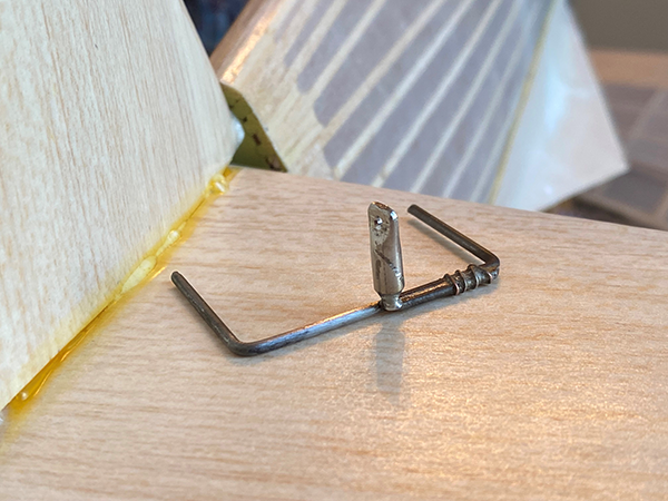
Hiding the linkage for the elevators was easier. This was done by silver-soldering a control arm directly to the elevator joiner rod. By locating the control arm in the middle of the joiner between the elevators, the control rod could be kept inside the fuselage and out of sight.
I’m not an expert at silver-soldering, but I have learned a couple of things. The first is to wrap thin copper wire around the parts to be soldered or crimp parts together with brass tubing. This holds them in position while they are heating, and the solder quickly wets to the copper and brass. The second thing is to use the heat from the torch sparingly. I use a small oxygen MAPP gas torch. It has a tiny flame and very little dwell time, but it is enough to get the silver solder to flow without taking the temper out of the music wire.
After the control arm was affixed to the joiner rod, the elevator control rod was fished from the elevator servo through a notch in tail former F12. Because the control rod was long and much of it was unsupported, I used a length of carbon-fiber tube with a music wire Z-bend epoxied in the tail end, where it engaged in the elevator control rod.
A bit of straight music wire was epoxied into the other end, where it engaged a Du-Bro E-Z Connector in the servo arm. After relieving a small pocket in the rudder, the result was a tight elevator linkage that was hidden from view.
Belly Pan and Cowling Flaps
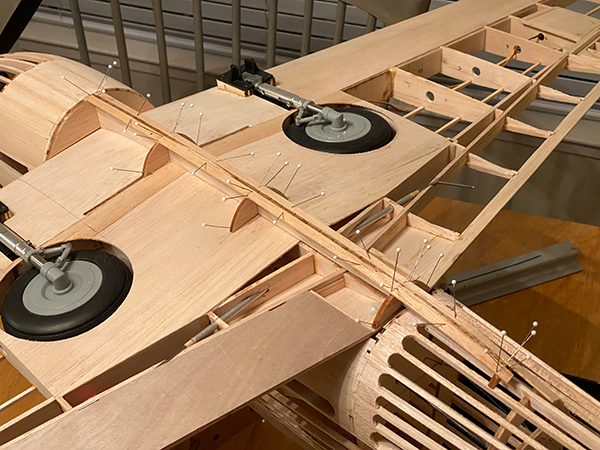
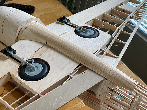
The belly pan on the P-40 is similar to the P-36, except that it is much longer, extending past the wing’s trailing edge. Construction began by pinning front pan former B1 to the back of fuselage former F4. Belly pan keel B2 was then aligned with the center wing ribs and glued to part B1. When cured, the pan assembly was removed, the rest of pan formers B3 through B6 were glued to the pan keel, and the assembly was pinned back in place.
The pan was planked with 1/16-inch balsa strips. Using 1/4-inch wide planks made the job go quickly, while planking with the pan in place ensured that the result would snugly fit the underside of the wing and fuselage. Two 1/8-inch pins were used to fit the front of the pan to the back of former F4 and pan former B5 to the wing. A pair of magnets held the pan tightly in place. Because the P-40 pan is slightly wider than that of the Hawk, it completely covered the wing attachment screws.
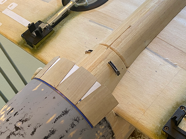
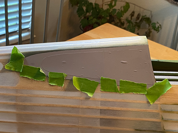
The cowling flaps behind the chin of a P-40 are key to the character of this aircraft’s personality. For the prototype, I used 1/64-inch plywood to make the four cowling flap panels. A strip of scrap balsa was glued to the back edge of the chin scoop. This strip held the panels in the partially open position when the front edge of each panel was seated against the scoop and the middle of the panel against the strip.
After the panels were at the angles I was looking for, a paper strip was glued to the inside of the panels to hold them together and to represent the inner layer of the full-scale flap assembly. After sealing the flap assembly, it was glued to the back of the chin scoop.
Covering and Paint
With the construction completed, it was time to begin covering. The chin scoop received two layers of 1/2-ounce fiberglass cloth to protect it from future nose-overs. The belly pan was sealed with lacquer, sanded, and covered with tissue paper and waterborne polyurethane.
The rest of the airframe was covered with Polyspan fabric. This was attached with Mod Podge and sealed with waterborne polyurethane. After ironing the sealed covering, the model was painted with latex house paint.
A full description of the covering and painting processes can be found in the October 2015 issue of Model Aviation.
Installing the Plastic Parts
The side windows were cut from thin plastic sheets that were salvaged from vacuum-formed salad containers. The window outline was lifted from the side view on the plans. After marking the outline on the plastic, each window was cut out using a pair of curved scissors.
The side window openings were prepared by filling the areas between the stringers and around the windows with scrap balsa. The panels behind the windows were carefully sanded down so that the side windows would sit slightly proud from the frames as they do on the full-scale aircraft.
The canopy and side windows were then masked and sprayed with three coats of high-build automotive primer to build up the window frames. After the primer dried, these parts were epoxied in place.
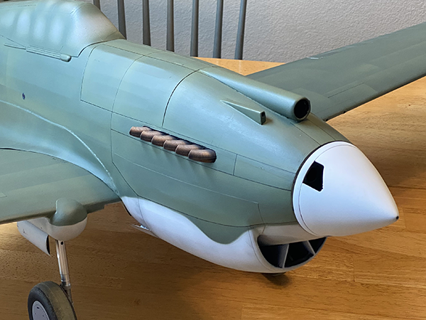
The last parts to be installed came from my buddy Shane and his 3D printer. These were a pair of early-style Allison V-12 exhaust stacks and a spinner. Both were designed specifically for this kit so that they perfectly fit. The STL files are available as free downloads on Thingiverse.
The exhaust stack openings were cut out using the outline on the plans. A crutch made from scrap balsa was glued to the back of each stack. The front of the crutch attached to the back of former F2 and the rear of the crutch was glued to the inside of the fuselage skin.
Flying the Infield Engineering P-40C
At 2-1/2 years, this build was one of the longest for me. It wasn’t that it was complicated but rather that life got in the way. To be honest, because it took so long to complete, the butterflies were more active on the day of the finished the aircraft’s maiden flight.
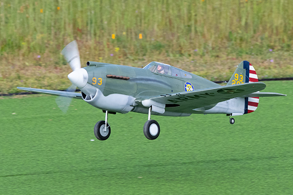
The weather conditions were perfect and my photographer friend, Paul Gibson, was well prepared. After a preflight discussion and a quick taxi test, the P-40 was lined up with the center of the runway. Power was slowly added and soon it was rolling. It was easy to steer on the short astroturf surface. The tail came up more quickly than the P-36—the longer nose provides more leverage. A fair amount of backstick was required to keep from digging the propeller into the runway.
After trimming out a tendency to roll right, the P-40 settled into a series of photo passes. These were flown at surprisingly low speeds. With a 60-inch wingspan and weighing 5.5 pounds, I felt very comfortable flying low and slow on the first flight.
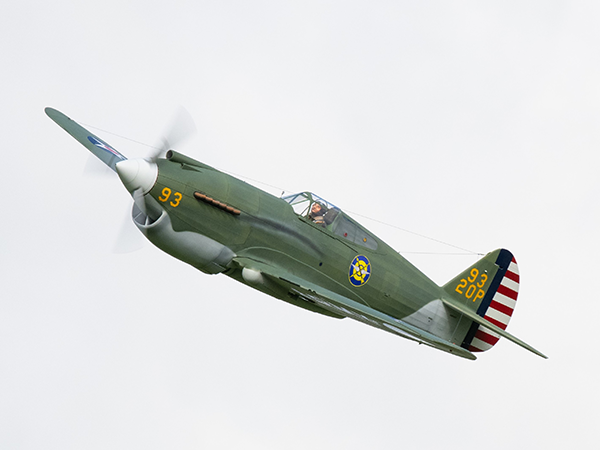
When the photos were in the bag, it was time to see what the P-40 would do. Some giant loops, slow rolls, and a couple of Cuban 8s felt solid. I was less thrilled with the Master Airscrew 14 × 7 propeller than the FMS 14 × 8 on the P-36. Both models have the same powerplant, but the draggy radial-powered P-36 felt significantly stronger and sounded much better. Master Airscrew doesn’t offer a 14 × 8, but I’ll give the company’s 14 × 9 a shot next. It weighs less than the FMS propeller, and the P-40 doesn’t need more nose weight.
The landing should have been a breeze, but to be honest, we went back to flying more photo passes and I lost track of the time. After hitting the low-voltage cutoff, the landing was a bit of a panic. I did manage to get the gear and flaps down, but I botched the first approach and put the model down a little hard on the second. It was not the airplane’s fault, but at least you know now that this is an honest flight report.
Thanks for Following Along!
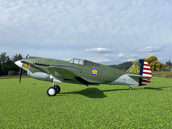
And this brings us to the end of this project. Overall, I’m pleased with my P-40C prototype. It has that great, sharky attitude that the early P-40s are known for, but without the actual shark mouth motif that is arguably overdone. As a tribute to the U.S. Army Air Corps pilots who passed over my small hometown in 1941, I’d like to think that seeing this model take to the Sonoma County, California, sky would bring a smile to their faces.
SOURCES:
"Fighter Face-Off"
Manzano Laser Works
Infield Engineering Curtiss P-40C Spinner and Detail Parts
Thingiverse
www.thingiverse.com/thing: 6601260


Comments
Add new comment