
Written by Keith Sparks Construct This Giant Scale Foamie B-52 Build Article As seen in the October 2018 issue of Model Aviation.
Download free plans
Image

Document
Order Plans from AMA Plans Service
Image
Image
Specifications
Wingspan: 82 inchesLength: 72 inches
Weight: 8 pounds
Wing area: 787 square inches
Power system: Eight Dr. Mad Thrust 40 mm eight-blade EDF 800 Kv motors (330 watt); eight 26-amp ESCs; two 3S 4,500 mAh LiPo batteries
Power output: 1,132 watts; 108 amps
Flight time: 6-plus minutes
Image

As RC models go, I have always thought of the B-52 as a glider with swept wings. Back when we were all flying with brushed motors and NiCd batteries, I made a B-52 as a twin propeller-driven model with a 3-foot wingspan. With its wide wingspan, long moments, and generous surface areas, it did well. The availability of today’s small EDF units made me want to take another run at a larger B-52. Its development was completed in several test-flight stages. The first was a hand-launched glider, the second one was propeller driven, and finally it was powered by eight EDF units. The foam slab construction was from a single sheet of 3/4-inch extruded foam. The wing is cut from expanded bead foam to save weight and sheeted with a thin layer of extruded foam. This building method was covered in Model Aviation (February 2016) as part of a series of foam construction methods. My book, Building With Foam, goes in-depth on all aspects of foam construction and would make a great reference from which to draw while working on this and future foam projects.
Construction
The fuselage takes shape quickly because it is simply a tapered box. Patterns from the plans are used to cut the side, top, and bottom panels. The panels are bonded together with the fuselage top against the work surface to ensure that it remains straight. This is important because the fuselage top is the datum reference for all measurements.Image

The fuselage material comes from a home-improvement store in the form of 3/4-inch foam insulation sheets. The sheets make up a simple, tapered box with the corners sanded round. Assembly can be done in a single afternoon. A soft pad on the workbench is used to prevent dents.
The front of the fuselage includes compound curves, so the nose requires a little sectional construction. Patterns are taken from the plans to cut 10 disc-like sections from the foam sheet. This method makes it easier to make the nose shape of the model. The discs are tack-bonded together using their centerlines and waterlines as a reference.
Image

A little sectional construction is needed to capture the shape of the nose. A hobby scroll saw makes short work of this step. Leavening the sections solid would provide a good place to store ballast for a Slope Soaring glider version.
The nose assembly is bonded to the front of the fuselage box—tack-bonded if you want to hollow the nose later or completely bonded to store ballast if you plan to construct a Slope Soaring glider. Sanding the fuselage to shape is accomplished by simply rounding the corners of the box with a long sanding bar then shaping the nose. I start with 90-grit sandpaper then reduce the grit as the fuselage gets closer to its final shape, finishing with 180-grit sandpaper. This two-hour step is best done on a padded surface, outside on a windy day. To cut the battery hatch from the fuselage, I used a replacement wallpaper scraper blade because they are so long. The cuts have to be angled slightly inward so the hatch will be easy to use. When it has been removed, the hatch hole is lined with 1/16-inch balsa to make the edge tough. The hatch cover edges are marked at 1/8 inch and block sanded to the line. This removes the space necessary to cover the edges of the hatch with 1/16-inch balsa. After several test-fits, the hatch can be sanded flush to the fuselage bottom. I recommend coating every completed part with one layer of 3/4-ounce fiberglass cloth as soon as possible to prevent damage to the foam surface during the rest of the construction. As components are completed, one ply of 1/2-ounce fiberglass cloth is applied on top of the heavier cloth. This finer weave makes it easier and faster to get through the weave fill steps and achieve a smooth, paintable surface. The wing cores are cut from expanded-bead foam panels using a hot-wire method. The aspect ratio of this wing makes the cut difficult so plan to make more than two panels for a little practice. Use the plans to draw lines on the bottom of the panels to locate where the spars, wiring, and pylons will be located.
Image

Before the wing cores are sheeted, grooves are cut in the foam with a rotary tool. The wiring harnesses are installed and tested. Afterward, the grooves are filled with foam strips or wood where they add strength.
Use your rotary tool to cut grooves in the wing core to accept this hardware. The spar tube groove is cut parallel to the top of the wing; use the wing cap pattern for the depth reference. The wing root cap is also used to locate the spar hole positions on the fuselage.
Image

The tail surfaces are made with solid foam panels. They are shaped with the use of plywood sanding guides because of their aggressive taper. This is easier than it sounds if you let a sanding bar do the work.
After the holes are cut, the wing cores and spar tube are mated to the fuselage. The fuselage and top of the wing panels are supported level to the work surface while the epoxy sets up on the spar sheathing. Now that the spar tubes are mounted, the wiring is installed and covered with wood strips that will add strength. The rest are filled with foam strips. The wing core panels are sheeted with 3 mm craft foam sheeting, or you can cut your own sheeting from the 3/4-inch extruded foam. This sheeting method offers a smooth surface for the fiberglass work and prevents the expanded bead foam from soaking up the fiberglass resin. Use Gorilla Glue to bond the sheeting to the wing core. Nesting the wing in the core beds with applied weight will ensure that the panel stays straight and true. Before bonding the second sheets to the panels, poke location holes in the top sheeting at the pylon mount locations. The B-52’s tail feathers have a basic fin and rudder arrangement; however, for absolute pitch control, I went with a stabilator. This uses a brass tube as a pivot pin and aluminum tubing as a bearing surface. Actuation is accomplished with a bellcrank coupled with a control pin near the leading edge. The panels are made with solid extruded foam cut from the 3/4-inch sheeting using patterns from the plans. Plywood sanding guides are bonded to the tip and root along the centerline. The airfoil shape is accomplished by sanding away the foam until the sanding bar reaches the plywood guide. A balsa strip is applied to the edges of all three panels for bump protection, and the rudder hinge line is cut and lined with balsa to form a hard surface for the hinges. To mount the tail surfaces to the fuselage, start with the fuselage on its back and the sides square to the work surface. A small portion of the fuselage belly is cut free and retained to be installed later. The hole for the stabilator pivot tube is drilled in the fuselage, along with the control pin slot. Grooves are cut in the stabilator panels, as were the spar tubes in the wing. The brass and aluminum tubes are threaded through the fuselage and the aluminum tubes are bonded to the stabilators. Now that the panels can slide on and off the brass tube, the control pin can be installed and tested for freedom of movement. The control pin is moved with a bellcrank that is made from laminated aircraft plywood. One end has the servo pushrod attachment, while the other has a slot that engages the control pin. The support for the bellcrank pivot is also made out of plywood and is installed by pushing the blade end against the foam sheet, leaving a dent. Slots are cut in the dent positions and epoxy is used to bond the support to the fuselage. Test the bellcrank’s position and operation before bonding.
Image

Pitch control is provided with a 1/8-inch pin connected to the front of the stabilator. The pin slot can be seen on the side of the fuselage. The fork cut into this bellcrank engages the pin to move the surface. It is constructed with laminated, aircraft-grade plywood. The attaching hardware threads receive a touch of CA adhesive before installation.
Install the stabilator servo and route the pushrod in place, supporting it between attachments to prevent bowing. As for the fin and rudder, I went with a pull-pull cable system and simply bonded the fin to the top of the fuselage. There is little room in the fuselage under the rudder hinge line to work, making the cable attachments hard to get right. Others have mounted the rudder servo in the fin. To set the wing angle of attack, slide the fuselage-to-wing-mount plate in place against the wing root cap with tape strips holding it in place. The wing is installed and used to hold the mount plates against the fuselage sides. The wing is supported at an angle of 3.5° with the trailing edge (TE) down. Epoxy is applied between the fuselage side and the wing mount plate. The holes for the wing bolt are drilled in the fuselage using the mount plate as a guide. Because the fuselage is so narrow, it is much easier to secure the wing with a nylon wing nut. This arrangement requires special hardware. A long nylon bolt with the head cut off is bonded in the wing, leaving the threads exposed. It is long enough to reach the inside wall of the fuselage. A plywood plate is bonded to the inside of the fuselage wall to prevent the nut from crushing the foam.
Image

The wing bolts extend into the fuselage so the wing nuts can be installed. The plywood plates prevent the foam from being crushed. The happy mistake here is that the foam panel interferes just enough with the wing nut so that it prevents it from working loose. The yellow tube is the spar sheathing.
Image
Plywood plates are used during the wing attachment step to set the wing’s angle. A T-square is used as a sanding guide for the wing fairing. The marking on the fuselage is from the author’s glide testing to find the best CG and wing angle.
The wing fairing is made from scrap foam sanded to the radius of the fuselage. This is accomplished by wrapping the top corner of the fuselage with sandpaper and rubbing the scrap foam against it. The piece is bonded between the fuselage and the wing mount plate then sanded to match the wing profile. The motor pylons are made from two lightweight plywood panels with balsa spacers to form the conduit for the wiring. To install them, the fuselage and wings are placed on the work surface inverted with the wing supported equally above the surface at the TE.
Image

To mount the pylons, you need a line level and a heavy square block as a bonding fixture. Using slow-setting epoxy will allow plenty of time for measuring and adjusting. Practice threading the wires through the pylons before mixing the epoxy.
The pylons are bonded to the wing through the pylon slots and attached to the wing spar. Using a block and clamp to hold the bottom of the pylon level with the work surface makes the task easier. Slow-drying epoxy will buy you time to ensure that the bottom of the pylon is parallel to the work surface and fuselage centerline. Small fan units do not have mounting flanges so a mount must be made that can be bonded to the pylon. For accuracy, I used the fan shroud as a form tool to laminate 10 strips of 3/4-inch contractor’s paper with wood glue. An alternate material would be a paper grocery bag.
Image

A block with two-sided tape stuck to the nacelle nose holds the fan units in place while the motor mount epoxy sets up. Playing cards were used to adjust the block angle, which was checked with a level across the fan units.
After the paper has completely dried, the mounts are cut to wrap around the fan shroud by slightly more than half. The paper mounts are then bonded to the fan shroud using silicone and rubber bands for clamp pressure.
Image
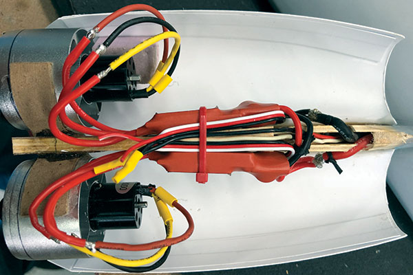
Mounting the ESCs on the pylon inside of the nacelle will eliminate any cooling problems. Their position probably reduces thrust without a blast tube attached. Note that the motor insulation had not been shrunk yet because a test run had not been accomplished. Five out of eight motors turned the correct direction.
To mount the fan units, I used the formed plastic nacelle nose to set the position of the fan shrouds. Two-sided tape held them against the square block while a stack of playing cards was used to level the fan units. Drops of epoxy glue were applied between the paper mounts and the pylons to complete the installation. The nacelles are vacuum-formed with High Impact Polystyrene plastic in three pieces. B-52 nacelle sets are available from Park Flyer Plastics. The upper nacelle is bonded to the pylon and supports the lower nacelle. The nose/inlet is bonded to the lower nacelle with plastic cement and engages the fan units to further support the lower nacelle. Two screws hold it together, offering easy access to the equipment. After the inlet is bonded to the lower nacelle, slide the assembly into the mounted fan shrouds. The upper nacelle slides into place around the pylon and is mated with the lower nacelle and nose/inlet. Masking tape is applied to the nacelle and pylon contact point to hold it in place. The lower nacelle is removed and epoxy is applied to the nacelle-to-pylon fairing. Wiring eight EDF motors is not without controversy. Everyone has opinions on what works best. I like to keep it simple. The power wiring for the motors is a basic wire bus with a reduction in wire gauge toward the outboard ESCs to save weight. After several test runs, it was determined that capacitors are needed near the ESCs to stabilize the power draw at high settings. With eight ESCs running, the BEC also introduces problems when the battery power gets low. They tend to “argue” over which one gets to shed its load first, causing voltage changes that bring the rest to enter the “conversation.” Disconnecting the red wire at all of the ESCs stops the argument. This requires installation of a separate BEC for the radio equipment. Adding a flight battery is another option, but it adds weight and another battery to charge. Mounting the ESCs in the nacelles against the pylon will keep them hidden and cool. Some think this arrangement robs thrust from the model, and it probably does, but not enough for me to notice. The other option is to mount them in a compartment cut in the bottom of the wing, leaving the ESC surface exposed to the slipstream.
Flying
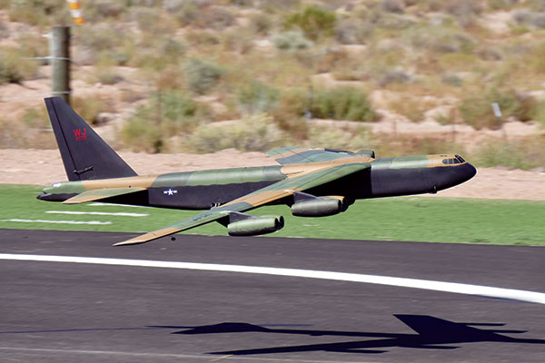
My first flight was as a glider to establish the best center of gravity (CG) and best wing angle of attack. From there, I put a temporary propeller on the nose to establish control throws and power requirements. After installing the fan units, the next test flight was going well until I started losing motors. I cut the throttle and was flying my glider again. Postflight inspection revealed that several motor mounts had failed, causing the fans to rub the fan shrouds and depart the aircraft. With better 40 mm units installed, the harmonic vibration problem went away and the extra power made the model come to life. I maintained flight at half throttle, so climbing to a more scalelike altitude allowed me to pull the throttle back more and coast for longer flight times. The roll rate is gentle and the model can be turned without the use of rudder, but it takes a little work. Coupling the rudder with the ailerons at 20% makes turns easy, but a steep bank angle will get you in trouble at slow speeds. My concern about the landing was that the motors would snag the ground when they should have been getting it to land. Expect to overshoot the runway on the first few flights because of ground effect. The upside to this ground-effect problem is that the wing is easy to keep level while landing. If you cannot find a flying buddy who you can trust to hand-launch your model, there are options. I went with the tail-dragger approach because I fly off of grass. This unusual configuration allows the model to rotate for takeoff. The wheels fall off when released and then I belly-land the aircraft. My friend, John Morgan, chose the scale configuration and went as far as making the gear retractable. The wing’s angle of attack allows the model to lift off without rotating. This prevents it from lifting off too early. John’s flight can be seen on YouTube by searching for “John Morgan B-52.” By searching for “B-52 7-foot span” on RCGroups, you can find my build thread as well as John’s innovations to the design. I want to thank John and Wade Joos for helping me get this design in the air.Image
—Keith Sparks [email protected]


Comments
b-52
This article is a god send. It will reduce the design of a bird I have been holding in reserve for quite sometime.
Keith is the MAN in my book! this hobby needs more articles of this type.
Keep up the good work..........................And THANKS!
Amazing foam construction and first flight
Amazing first flight: https://www.youtube.com/watch?v=9Ud6lDphyfs
need some help if you could please.
Hi, my name is David Hunt and my father was a tail gunner on the B52 he was with the 668th bomber squadron. "we maintain the Balance" my question is could do you have a much smaller scale ? I'm trying to carve this out of wood with saw and Dremel and only need a pattern and cant seem to find one. If not no worries have a great day and what an amazing plane you built
Construct this Giant Scale Foamie B-52
My question is:
1. Can you 3d print the plans? ( I think using carbon fiber. )
2. Can you equib it with jet turbines instead of the electric one's?
Add new comment