By Bob Benjamin [email protected] Photos by the author
As seen in the July 2022 issue of Model Aviation.
The Curtiss SB2C Helldiver is not an airplane that many aeromodelers typically choose as the subject of RC Scale building projects. The full-scale Helldiver was a second-generation design that followed the Curtiss SBC biplane dive bomber onto U.S. Navy aircraft carrier decks in 1943.
The SBC, a 1930s design, never had much opportunity to prove itself in actual combat. When the SB2C’s turn came along, it did not win a place among those World War II classic airplanes that are remembered today. There were so many " x-it" reports on the newer, larger Helldiver that the airplane’s suitability for service was questioned.
With most of the shortcomings dealt with, the SB2C was turned into an acceptable combat airplane, but it never became a great one. From the point of view of many of us who build and fly Scale models of those airplanes, it was not beautiful but rather funny looking. The pilots who flew it called it The Beast, among other things.
Similar to some other unusual airplanes, from a model builder’s point of view, the SB2C can grow on you. I knew about Helldivers from an old RC flying friend, the late Dick Carson, who flew them as a Naval Reserve pilot during the late 1940s while there were still a few of them on duty.
During a conversation with Model Aviation Executive Editor Jay Smith several years later, we were discussing various airplane types that might work as subjects for future construction articles. He asked whether I knew anything about SB2Cs. When I explained that I did, Jay shared a few old family stories about his great-aunt, who had helped build Helldivers as a "Rosie the Riveter" during the war.
One story that nearly everyone who builds model airplanes knows about is the one where a couple of friends share ideas about what to build next. Those conversations tend to turn into long, detailed discussions of all of the good things they might do with a (ll in your favorite airplane). Jay knew that I have a lot of experience doing rubber-power-to-electric RC conversions of old balsa kits that were intended for Free Flight (FF).
Easy Built Models has a classic stick-and-tissue SB2C kit. By the time that I was done imagining all of the possibilities, I had ordered two Dave Niedzielski kits that are based closely on the classic rubber FF plans that are included as part of the 1940s Model Craft kit.
Dave reminded me that this Helldiver kit was one of many vintage designs that he had acquired the rights to reproduce. Like many of its contemporaries, the kit engineering was basic, meaning that many of the structural details were left for experienced model builders to work out on their own.
These kits are historically correct, he suggested, which means that they are not for beginners! He was right. A quick check of those old plans revealed things such as a lack of any explanation for how to mount the tail surfaces to the fuselage, what provisions had been made for a wingspar center section carry-through, and more. Easy Built Models has been adding pictorial instructions to its website to assist with the construction of their models.
For contemporary kit suppliers to update all of those old rubber-powered kits to today’s standards would add so much time and expense that many would never be brought back at all.
It took me a while to come up with a plan for making the best use of those two kits to create a feature article that would be the most interesting and useful content for Model Aviation readers who love stick-and-tissue builds. In the end, I came up with two different model airplanes.
I built one kit as closely as possible to a box-stock 1940s rubber-powered FF aircraft, adding necessary details to make a practical flying model much as an experienced builder back in those days would have done. It is the medium blue, tissue-covered aircraft with the yellow tail marking. The other kit (the dark blue SB2C-4 carrying the call number 201) got the full electric-conversion treatment to become what those in the 1940s and ’50s would not even have dared to imagine.
Image
02. Here you can see the finished RC model from the same angle as the FF aircraft.
Readers might remember my Guillow’s kit conversions, especially the Spit re, that appeared in Model Aviation several years ago. The models that were built from those Guillow’s kits are far more substantial than this Model Craft design. They are also heavier, but decisions about which part belongs where are carefully explained on the plans.
My intent with those models was to control the weight by making material changes and/or substitutions. With this build, there was nothing to eliminate. Instead, I had to add quite a bit to be sure it would stay together for actual RC flight.
With my electric RC version of the Helldiver kit, I chose to invest the time and effort that were necessary to create an appealing, small RC Sport Scale model that grabs your attention and gets you thinking about building one (or any) of those available kits.
If you have enough balsa building experience to work on a stick-and-tissue-to-electric conversion, you don’t need specific parts, patterns, assembly sequences, and so on for what will probably be something different from other SB2Cs.
I’m showing you what I did with this kit to share some ideas that you can consider when you engineer the changes for your own model. I have included detailed photos to help explain what is going on.
Choosing a motor/battery/ESC combination for a new model is the subject for an article of its own, but I’ll share what I used on this project. There’s plenty of material that you can research on your own.
After that choice has been made, it’s easy to describe how to convert a kit such as this one in four basic steps: 1) adding a motor, battery, and ESC; 2) adding an RC system; 3) adding control surfaces for the RC equipment to control; and 4) adding or modifying the structure as necessary to hold those things in place.
Steps one and two were straightforward. I used components that I was familiar with from use in earlier models. This SB2C conversion includes a lot of adding and modifying, but one of the first choices that I made was to keep the "one-piece" rubber model design without a removeable wing. This allowed me to save a lot of the extra structure and weight that would be necessary to make that work. That was a practical option, in part because the long "greenhouse" cockpit enclosure provides convenient places to locate separation lines. The top comes off of this airplane to provide clear access to the entire inside of the fuselage.
Building two different SB2C models from a pair of identical kits gave me the opportunity to demonstrate and compare a range of Deluxe Materials products, especially Eze Tissue. This new product is based on a combination of natural fiber and synthetic materials. I have been working with John Bristow of Deluxe Materials to explore and document what can be done with what might appear to be merely better-quality, imported tissue.
Eze Tissue offers several advantages over traditional paper covering. I’ll point out some of these as the SB2C project progresses. The FF model demonstrates using Eze Tissue on a traditional built-up (open structure) balsa stick-and-tissue model.
I have included a quick look at the tissue-covered SB2C to give you an idea of how well it works. With the electric-conversion model, I will take a close look at some of the interesting ways to use several Deluxe Materials products that might seem unrelated on a more complex, closed-structure, sheet-balsa model.
Image
03. The electricconversion wing for the SB2C is simply the stock kit rubberpowered wing with some extra balsa added.
Image
04. Here’s a better look at the original FF wing structure according to the kit plans. This clearly shows the aileron location.
Image
05. The top surface sheet of the right wing half went on after the entire inner structure was sanded.
Image
06. Formers F1, F1A, FW-A, and FW-B were doubled in thickness.
Image
07. F1A and both FW parts make up an extra former.
Image
08. All of the forward formers are in place on the modified keel that was assembled over the fuselage’s side elevation for alignment.
Image
09. The side keel slots were cut out to make room for duplicate square balsa keels.
Electric Conversion
As shown in photo 03, the electric-conversion wing for the SB2C is simply the stock kit’s rubber-powered wing with some extra balsa added. The new wing is fully sheeted, top and bottom, with 1/16-inch balsa sheet. Before laying out this part of the structure, I edge-joined several 1/16 × 3 × 36 sheets of medium-soft balsa then traced one wing panel outline and used it to mark out four wing skins (roughly 1/2 inch oversize to compensate for curvature and provide a safe working margin).
I marked the basic rib, leading edge (LE), trailing edge (TE), and tip outline positions on what became the right-wing bottom surface then assembled those parts into the marked locations using Deluxe Materials Aliphatic Resin Glue.
While assembling this primary structure, I enlarged the LE from a 1/16 × 3/16 to a 1/4 × 3/8-inch balsa strip that was slotted 1/16 inch from the rear for each rib. After that, it was necessary to slightly trim the front end of each rib to compensate for the small remaining difference from the original material dimensions.
I retained the original 1/16 × 3/16-inch balsa TE, which is beveled to permit the top and bottom wing skins to cleanly meet. The aileron structure is added in the same position as the aileron outline that was drawn on the original plans, and the various notches in the ribs are opened up to that the modified spars. The cutout in the center will become the aileron servo well opening.
Photo 04 offers a better look at the original FF wing structure, according to the kit plans. The aileron location is shown clearly. I left out the diagonal braces because the 1/16-inch balsa top and bottom skins will do a better job of handling flight loads. The spar pattern drawing describes the changes I added. One of the original kit box labels is included in the photo just for fun.
In photo 05, the right wing’s top surface sheet was applied after the entire inner structure was sanded, with no bumps or protrusions that would prevent the balsa sheet from laying tight against every part. I used Deluxe Materials Aliphatic Resin Glue and applied it at every possible point of contact.
I assembled the top-surface balsa sheet wet, then held it in position with small shot bags to dry. This method causes the balsa sheet skin to shrink slightly as it dries, placing an even, prestressing load that helps prevent the finished structure from twisting.
Formers F1, F1A, FW-A, and FW-B, shown in photo 06, were doubled in thickness for reinforcement. FW-A (the primary firewall/motor-mount base) is 1/16-inch aircraft plywood. F1A is 3/32-inch balsa sheet and becomes the TE reinforcement for the cowling when it is cut free.
F1A and both FW parts make up an extra former that is added ahead of the scale firewall location, which should be at the rear edge of the cowling flaps. The cowling diameter increases slightly behind F-1 and the FW location.
To make F1A fit, I "eyeballed" an enlarged duplicate of the original. If you look carefully at photo 07, you can see where the printed/inked stringer notch locations on F-1 have been transferred to the new part with short pencil marks.
Image
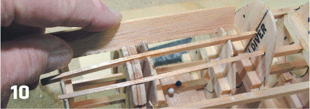
10. Getting the stringer notches on successive formers to align correctly can be difficult.
Image
11. The basic fuselage framework has been removed from the top of the plans.
Image
12. Here’s the fuselage at the same stage of construction, with the two wing panels joined at the correct angle and separated to match the rib W1 position, as shown on the original plans.
Image
13. This shows both sets of rib parts assembled.
Image
14. Both laminated W1 assemblies fit against the wing root base locations.
Image
15. The assembled wing is fitted into the fuselage tight against both laminated W1 assemblies.
Image
16. The soft, sheetbalsa inlays are cut to fit into the odd shapes that were created by the formers.
Image
17. The secret to success when doing work such as this is to never hurry.
The original kit fuselage is started by assembling formers F1 through F8 on a center frame/keel of 1/16 × 3/16 balsa. On the electric conversion, 3/16-inch square balsa was used for extra rigidity during assembly.
In photo 08, you can see all of the forward formers in place on the modified keel that was assembled over the fuselage’s side elevation for alignment. There is no complete bottom view on the plans. The slots for the 1/16 × 3/16-inch balsa side keels were enlarged for 3/16-inch square balsa strips that are aligned with the original top keel edge shown on the plans.
The side keel slots were cut out to make room for duplicate 3/16-inch square balsa keels that fit tightly against/above the lower ones, as shown in photo 09. The adjacent balsa strips will de ne the parting line between the removeable top deck and the fuselage.
There is much to see in photo 10. The odd, 1/4-inch square balsa crosspieces are former reinforcements to prevent splitting. The former at the top left is the stock kit F1 that was used as a pattern. The scale firewall position lines up with the rear edge of the cowling flaps on this plan, so F1A, the firewall (FW), and F1B are assembled as a stack of laminated parts that de ne the position. Getting the stringer notches on successive formers to align correctly can be difficult.
I made a custom sanding tool from a scrap of hard 3/32 balsa sheet. A 3/32 wide strip of 120-grit production sandpaper was glued to the narrow edge to make a perfect cutting tool for aligning slots in all of the F parts.
In photo 11, the basic fuselage framework has been removed from on top of the plans. You can see all of the top, rear, and side 3/32-inch square balsa stringers in place. The lower stringers will go in after the wing is in place.
I assembled the several separate W1 parts for each fuselage side with the 1/16-inch spacing for the formers maintained, cut out two duplicate complete W1 patterns, and then assembled both sets of rib parts, as shown in photo 13.
Both laminated W1 assemblies fit against the wingroot base locations (short, straight sections on the original parts) on F4, F5, and F6, as shown in photo 14. This location and dihedral angle follow the original design, which is based on the correct dihedral angle for the full-scale SB2C.
Photo 15 shows the previously assembled wing fitted into the fuselage tight against both laminated W1 assemblies, verifying the correct position of the wing in the fuselage. The remaining bottom fuselage stringers are also shown in place.
The soft balsa inlays are cut to fit in the odd shapes created by the formers coming together, as shown in photo 17. This is a proven method of modifying an open framework fuselage into one that is fully sheeted and surfaced.
Image
18. Here you can see the entire fuselage/wing/tail assembly all sanded out.
Image
19. Blue masking tape marks exactly where the cuts are to be made.
Image
20. Balsa-strip reinforcements were added to the inside face of each of the lower balsa side keels.
Image
21. The author brushed on a second application of Eze-Kote after the first coat had dried.
Image
22. Eze Tissue used as a topcoat weighed slightly less and allowed the author to add some color without a final paint coat.
Image
23. Wrap the free ends around and over the edges of the structure.
Building an inlaid fuselage such as this involves careful cutting and fitting. I assembled each piece of balsa separately, wet it with water to make it flexible, and used Deluxe Material Aliphatic Resin Glue. This is a messy, time-consuming process that will serve as the base for a superior, lightweight, smooth, and accurate surface when it is dry and has been sanded.
Before the inlaid balsa pieces go onto the bottom of the fuselage, root fairing blocks fill the irregular open spaces between the wing roots and the fuselage curvature that are defined by the positions of the stringers as seen in photo 17. The secret to success while doing work like this is to never hurry.
The tail surfaces in the original kit were not much more than balsa outlines. Laminating several sheets of 1/16-inch cross-grain balsa sheet to be cut to match those tail surface outlines was one of those changes I made to deal with RC flying. In photo 18, you can see the entire fuselage/wing/tail assembly all sanded out.
In photo 19, with the shaping and finish sanding done, it’s time to rede ne the top deck/fuselage parting line that is built into several formers, along with the new side keel assemblies. Blue masking tape marks exactly where the cuts are to be made.
A single-edge razor blade is wider than a No. 11 craft blade and easier to hold in place to follow the preexisting open joint between the 3/16-inch square balsa side keels that de ne where the cut is supposed to be.
During construction, the facing surfaces of F1A and the firewall were left as only a lightly tack-glued joint. Now it’s time to follow that separation joint with a razor saw to complete separation of the top deck.
With the top deck off, as in photo 20, you can see that 1/16 × 3/16-inch balsa strip reinforcements were added to the inside face of each of the lower 3/16-inch square balsa side keels. I did the same thing with the detached top deck to create a wider mating surface area when the finished deck is mounted.
Preliminary sheet balsa trays de ne what will be the battery, ESC, and receiver mounting areas. Holes in the upper wing skin provide clearance for the Robart Manufacturing 1/2A mechanical retracts that were originally planned, and the opening in the fuselage is for the RLG actuating connection.
The plywood landing gear mounting plates that were originally built into the wing were partly exposed by cutting away some of the bottom wing skin to match the landing gear assembly.
With those landing gear openings cut, the entire outside surface of the airplane has been defined. Now it’s time to demonstrate the use of a combination of several new products to add structural reinforcement that also provides a lightweight, excellent finish base. A piece of Deluxe Materials or similar 0.6-ounceper-square-foot fiberglass cloth was cut oversized for the lower surface of the right wing. In the past, I would have chosen either polyester or epoxy resin to bond this to the balsa and fill the weave. There’s a better way to do this now.
I brushed the fiberglass cloth smoothly out across the balsa skin with a new, water-based material that has no strong smell. Deluxe Materials Eze-Kote is a one-part liquid polymer adhesive that adheres the fiberglass cloth and also fills the weave.
In photo 21, I brushed on a second application of Eze-Kote after the first coat had dried (several hours) and all of the rough edges and overlaps were cleaned up with 120-grit sandpaper. Followed by another sanding with 220 grit, this second coat completes the fiberglassing without using any volatile hydrocarbon solvents.
Image
24. Here’s the bottom of the airplane with two coats of Eze-Kote securing the fiberglass cloth, a layer of pre-colored Eze Tissue applied wet with one coat of Eze-Kote, light sanding, and then a second application of Eze-Kote was sanded.
Image
25. These old Model Aviation Products pneumatic RLG units were left over from some EDF projects.
Image
26. Here’s the entire working section of the airplane with the top deck off.
Eze-Kote dries sufficiently to be trimmed and finesanded in several hours in a warm environment; however, Deluxe Materials advises that Eze-Kote will continue to polymerize "quietly," and within 10 to 14 days aftr application, it will increase in hardness to the degree that an even finer finish-sanding is practical.
That’s not all! That fiberglass surface should still be primed and/or filled and sanded to provide a good base for the final color finish. That fiberglass/Eze-Kote surface still should be primed or filled and sanded again to provide the base for an excellent painted finish. Instead, using Eze Tissue for a topcoat is slightly lighter and allows you to add some color without a final paint coat, as shown in photo 22.
Deluxe Materials Eze Tissue is a new synthetic and natural blend of fibers that is intended for lightweight, rubber-powered FF models. It has an advantage over traditional tissues because when it’s sealed/finished with Eze-Dope, it will not continue to shrink after application and warp (or even crush) delicate structures.
I used pre-colored (dyed) Eze Tissue that was applied to the solid/sheeted surface of this model using more Eze-Kote instead of primer or paint. The Eze Tissue has superior wet strength and follows the compound curve perfectly.
As with any tissue or other fabric covering, it’s a good idea to keep pulling and stretching the covering out toward the perimeter of the structure that you are covering.
With everything stretched out smooth and tight, it’s easy to brush a generous coat of Eze-Kote out to the perimeter and wrap the free ends around and over the edges of the structure, as shown in photo 23.
Photo 24 shows the bottom of the airplane with those two coats of Eze-Kote securing the fiberglass cloth and a layer of pre-colored Eze Tissue applied wet with one coat of Eze-Kote and light sanding. A second application of Eze-Kote was also carefully sanded.
The Robart Manufacturing mechanical retracts are screwed in place with flexible tube-in-cable drives linked to a retract servo in the fuselage. (I could not find a commercially available electric RLG that was shallow enough to fit inside the depth of this wing. These were the best compromise available.)
At this point, I could have chosen to add a single topcoat of Eze-Kote to seal those sanding scratches and provide a fine, clear, dyed-tissue finish. Instead, I brushed on a final color coat in the form of Tamiya Color Acrylic Paint that was custom-mixed to approximate 1940s Navy Gloss Sea Blue. All of the markings came from Callie Graphics.
The Cobra 2204-40 brushless motor is mounted directly to the balsa spacer box that was designed to align it with the front of the cowling. The non-scale blisters on each wing (cut from craft store plastic eggs) clear the protruding portion of the Robart 1/2A retracts that would otherwise stick out through the top skin.
In the end, my struggles to get the mechanical retracts to work were for nothing; there was insuffcient down-lock to keep them from collapsing, even in gentle taxiing turns. I went into my stash of scale goodies and found old Model Aviation Products pneumatic RLG units (photo 25) that were left over from some EDF jet projects. They worked!
To avoid causing a delay in getting the model flightready, I decided not to remove the blisters and refinish the top of the wing.
Beneath the top deck (photo 26) are an E-Flite 22-amp BEC ESC, a Venom Power FLY 450 mAh 3S LiPo battery pack, the air valve and actuator servo for the RLG, a Spektrum AR630 AS3X SAFE receiver, and the Spektrum A2020 elevator and rudder servos.
Project Finished!
Two Helldivers! The external dimensions of both models are the same, as are the airfoil and flying surface incidence angles.
The FF model weighs 3.1 ounces, but the scale landing gear plugs in and is removeable for flight. With the wheels and landing gear removed, it weighs 2.4 ounces. The RC electric conversion comes in at 19 ounces with a 450 mAh 3S LiPo battery onboard. The wing loading works out to roughly 24 ounces per square foot.
Written by Pat Tritle Build the last dive bomber operated by the Navy Product Review As seen in the March 2019 issue of Model Aviation. Download free plans! Full-size plans Tiled plans Order Plans
Written by Richard Ryan Converting a Sig Goodyear Racer into a spirited electric CL trainer Construction As seen in the June 2017 issue of Model Aviation. Bonus video Specifications Wingspan: 24
Review Buzzard Models Fokkerish DR1 By Stan Alexander | [email protected] Photos by the author As seen in the June 2022 issue of Model Aviation. AT TIMES, YOU MIGHT WANT something different than


Comments
Add new comment