Written by Frank Granelli
Digital exclusive review.
Its slow flight is excellent, its initial and operating costs are low while it can be exciting to fly if pushed.


Maxford USA, famous for its high-quality line of unusual scale ARF aircraft, has recently introduced another unusual airplane, the Mentor-G Basic Trainer. The “G” stands for “Gasoline” as the Mentor is designed to use a 26cc class gasoline-fueled engine. The larger powerplant enables the Mentor-G to be larger and easier to see and fly than are most Basic Trainers.
This highly prefab ARF spans 83 inches with 1,187 sq. in. of wing area. That’s 1,187 square inches of wing in case you missed it the first time. Very few Basic Trainer ARF aircraft reach anywhere near this size; if any actually do. As Sport Aviator has learned from its testing of .60-sized glow-engine trainers, the larger airplanes are easier to fly and to see.
Since the Mentor-G is about 14% larger than 60 size trainers, maybe it will be 14% easier to fly? We’ll find out about that during the flight tests but one thing is for very sure right now. Since the engine burns gasoline instead of expensive glow fuel, the Mentor-G is certainly going to be lots cheaper to fly.

While Maxford USA is known for their line of uncommon, high-quality scale ARF aircraft, they are equally renowned for their extensive factory prefabrication. The Mentor-G is no exception as much of the hardware installation work, including engine mounting, was completed before the airplane left the factory.
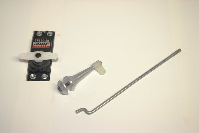
The main airframe components are shown in photo 1. Although larger than most Basic Trainers, the Mentor-G builds the same way as its smaller brethren. Many of the construction details will be covered here but you might want to review Sport Aviator’s 3-part article series about “Building An ARF Trainer” for truly in-depth construction details.
The Mentor-G’s 83-inch wing, while not a plug-in style, can still be stored and transported in two halves. The wing halves are not epoxied together. They slide together over an aluminum spar and are held together during flight by the twin rear mounting screws and front plywood “pins”. The wing saddle itself and two factory-installed wooden anti-rotation pins keep the wing aligned for flight.
CONSTRUCTION
Building the Wing:

The simplicity inherent is the wing’s design reveals itself in the ease of its construction. There is not a lot to do. Maxford has already cut the hinge slots for the giant sized CAA hinges in both the wing’s trailing and the ailerons’ leading edges. For complete CAA hinge installation details, read the Sport Aviator article “Installing Mylar Hinges”.


The Mentor-G’s CAA hinges are larger than those on the average trainer and they extend further into the trailing and leading edges than do most standard sized CAA hinges. Drill two 3/32-inch holes in each of the hinge slots as shown (photo 3). These holes allow the thin CAA to penetrate completely into the deeper inner hinge recesses. Insert two pins along the hinge center line (photo 4). Then insert the hinges into the control surfaces. Push the aileron firmly against the wing’s trailing edge until the aileron rests completely against the pins. Make sure that all hinges are inserted correctly. Then remove the pins, push the aileron further in until it is firmly against the trailing edge. Bend the aileron upwards and, from underneath, apply the thin CAA. Repeat from the top after the bottom CAA is dry.


Once the aileron is hinged, attach a 12-inch servo lead extension tothe aileron servo wire. Secure this extension either with string as shown or with 1/2 inch heat shrink tubing. Then use the factory installed string to pull the extended servo lead through the wing and out the hole in the underside of each wing half.

Seat the aileron servo in its mount and screw in place. The Mentor-G uses sturdy, lightweight aluminum control horns. These mount with a single bolt through the aileron. To position the control horn, attach the factory aileron connecting rod to the servo arm and the control horn. Position the control horn so the rod is perpendicular to the aileron’s leading edge. Hold the control horn in place and use a pencil to draw a circle around its base.
Remove the horn and place the top control horn “washer”, this part has a bolt hole in its center, inside the circle and mark the center bolt hole position. Then just drill through the aileron. Insert the bolt from the top through the top “washer” and screw the control horn in place.

The provided aileron control rod might seem slightly longer than needed. The extra length however, is there to make the bend as shown. This bend raises the control rod clevis from the servo near the wing’s undersurface up to the tall control horn. Complete both wing halves and be sure to center the ailerons.
If you wish and have a computer transmitter that allows it, the ailerons can be set to lower as flaperons. However, the flaperons can only be practically lowered about 15 degrees before the downward deflecting flaperon will jam against the wing’s trailing edge when full aileron is applied.
Frankly, at 15 degrees deflection, any flaperon effect is not noticeable. There is certainly no pitch trim change when flaperons are deployed. But even without flaperons this airplane will fly so slowly that it can, if pushed, remain flying at airspeeds under those needed for the ailerons to function. When flown this way, adverse yaw becomes far more of a concern than stalling at slow airspeed. This will be discussed in more detail in the flying section.
If you are not using a computer transmitter that allows differential adjustment, build some into the ailerons mechanically. This is done by locating the servo control arm two “clicks” (gear tooth spaces) towards the wing’s leading edge. The result is that the aileron deflecting upwards moves further than the downward heading aileron.
Slide the completed wing halves together over the spar. They should join tightly in the center with the anti-rotation pins firmly imbedded in the opposite wing half. Test fit the wing to the fuselage. This airplane’s wing fit well and its alignment was perfect. Test yours to be sure but exact and correct tolerances are a Maxford USA norm in all their kits I have tested to date.
The wing is complete. Assembling it required about 2 hours total. That’s not too bad for 1,187 square inches of wing. Did I mention that this wing has 1,187 square inches of lifting area?? If I didn’t, it does.
Assembling the Fuselage:
Select your powerplant before starting fuselage construction. Engine installation is usually best accomplished first, before attaching the tail feathers. It is easier, and reduces hangar rash, to rotate and position the large fuselage minus those big rear end pieces.


The engine chosen for this airplane is the CF26i from CRRC-Pro. This 26 cc (~1.56 cu. in.) engine is available from Maxford USA. It produces about 2.4 hp @ 9,000 rpm. The mounting bolt holes are factory drilled in the Mentor-G’s firewall. Maxford USA offers a combination package of the Mentor-G ARF with this engine for just $399. Since the kit usually costs $240, they are offering the gasoline engine for just $160. That is a hard deal to beat anywhere.
To date, I have flown the Mentor-G, with this engine, for about five hours with no engine problems of any kind. The idle is consistent and reliable at around 900-1,000 rpm. The engine’s power output yields a great climb rate and can even pull the modified flat-bottomed airfoil trainer through consecutive outside loops. If you do not yet have a 26 cc gas engine, I would suggest you consider the GF26i. It has proven a super deal so far.
The GF26i includes the stand off mounts, ignition system, spark plug and wrench, all mounting bolts and blind nuts and an installed velocity stack for that little extra power that just might come in handy someday.


Although the engine included standoffs, they were slightly shorter than was needed. This was covered in the Mentor-G’s instructions. Carefully peel back the covering as shown (photo above left) cut away enough wood to clear the engine’s cooling fins and muffler. Then re-install the covering using a covering iron. The result will be a clean finish as if the airplane was made that way. The bottom firewall mounting holes are close enough to the firewall’s triangle support blocks that the base of the standoffs hit the brace. Carefully remove enough brace wood to clear the standoff base as shown (photo above right) so that the base sits firmly and squarely against the firewall.
Special Note: The Mentor-G required significant nose weight to balance at the proper Center of Gravity (CG). It needed 14 ounces to be exact. My suggestion is this:
Purchase standoffs that are 1/4 to 1/2-inch longer than the stock ones that arrive with the GF26i. At ~2.5 lb, this engine is lighter than many 26 cc class engines. Locating it slightly more forward will not significantly alter the thrust line or aircraft performance. But it will eliminate some of the required nose weight. I am going to try this on this Mentor-G and hope to reduce the extra nose weight by as much as 4 to 6 ounces. Longer standoffs would also mean that the fuselage would not have to be cut for engine clearance. But that will be in a future update.

The ignition module is located against the firewall. Make sure that there is sufficient padding, here foam was used, to protect the module against vibrations. The module wiring is routed out the firewall hole as shown. The fuel lines also have to be routed out that firewall hole so do not cover it with the module.
Because I wanted to have the ignition battery as far forward as possible, I used a 4-cell, 1650 mAh Nickel Metal Hydride (Ni-MH) flat battery pack. This pack fits under the fuel tank. Many pilots prefer to use a 2700 mAh ignition battery but that would need to be mounted over the fuel tank and slightly further to the rear. The choice is yours.
The Mentor-G includes a wooden throttle servo mounting tray that can be positioned anywhere your particular engine requires. Install the servo in the tray and position the tray in line with your engine’s throttle control. Use the provided control rod. Since this is an ignition engine, install a nylon clevis to the throttle rod. Even though modern 2.4 GHz radio systems are supposed to be resistant against engine ignition “noise”, it is still a good idea to insulate the radio system from any potential interference.
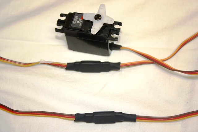
Install the elevator and rudder servo before attaching the tail feathers. It’s just easier to do this before having to work around the big horizontal stabilizer and vertical fin. Attach the extension servo leads and fix in place using 1/2-inch heat shrink tubing. If you prefer to tie the rudder servo extension in place as was done with the aileron servos, that is OK. But the elevator servo is too vital to chance a less secure method. Use the heat shrink tubing and shrink it in place with the covering heat gun.

The fuselage has a large slot for the stabilizer. Measure along the trailing edge of the stabilizer and mark the center point. The airplane has an internal top and bottom full sheet that glues to the stabilizer. It is not possible to see the stabilizer top once it is inserted into the fuselage so there is no need to mark the center leading edge as it is invisible.


Insert the stabilizer and center the trailing edge in the fuselage. Then measure both leading and trailing edges so that they are equal on both sides. This should center the stabilizer.


Measure and insert a pin into the center of the fuselage at the rear of the wing saddle. Then measure from that pin to the outside stabilizer trailing edge on both sides. Adjust until they are exactly equal.


Once the stabilizer is in position, mark the fuselage position on the top and bottom of the stabilizer. Remove the stabilizer and draw lines 1/16 in. inside the fuselage position (photo above right).


Use a hot knife to cut along the inside lines you drew. The hot knife cuts, actually it melts, the covering without cutting into the wood which would weaken the stabilizer. Remove the covering on both sides as shown.


Insert the stabilizer back into the fuselage. Since this is a flat bottom wing, we can use the wing saddle to level the fuselage. Place a small level at the rear of the wing saddle and adjust the fuselage until it is level. Place another small level, an appliance level works well, on the stabilizer. It should be level. if not, adjust the stabilizer saddle using a fine sanding file until the stabilizer is exactly parallel to the wing saddle.
This is very important. The stabilizer can be 1/32 inch longer on one side or have a leading edge 1/32 inch more forward than the other with little or no effect of the airplane’s flight characteristics. But a stabilizer that is not perfectly parallel with the wing will always induce a rolling moment whenever the elevator is applied.


Once you are satisfied with the stabilizer alignment, remove the stabilizer. Protect the fuselage with low-tack masking tape around the stabilizer slots as shown. Then brush 12-minute epoxy (a little extra working time is a good thing) into the slot making sure to coat the top and bottom plates.
Then use a paper towel to remove any epoxy for about 1/32 inch from inside the slots. This prevents the epoxy from escaping out onto the fuselage sides around the slot.

Slide the stabilizer into the slot then align everything again. A pound of weight was needed to keep the stabilizer level with the wing while the epoxy cured. After the epoxy cures, install the elevator as was done with the ailerons. Do not forget drilling the holes in the hinge pockets.

Install the elevator control rod and horn as was done on the ailerons. The fuselage does have a second servo mount on the right fuselage side should you wish to add a second elevator servo. In this case, the rudder servo would be mounted in a third servo mount, covered, on the fuselage top just in front of the vertical fin.
I don’t quite understand this since the elevator is not very large. Any ~70 oz in. servo is more than sufficient to handle the load. This airplane is already tail heavy without the third servo so I would strongly suggest using a single, 70 oz. in., or stronger, elevator servo.
I used a Futaba S3305 servo. At 124 oz. in. (6 volts) and having metal gears, this servo probably could pull the elevator all the way up to the top floor of a high-rise. (Maybe that’s exaggerating but you get the idea.). The servo is a little slow at .20 sec/60º but this is a Basic Trainer after all and lightning-speed elevator response would not only make it not fly better but could be a negative with very new students.

Install the vertical fin in the same way as the stabilizer. Remove any covering where the epoxy must be applied in the same manner. Use a triangle to insure that the vertical fin is 90 degrees to the stabilizer. See how important it always is to insure the stabilizer is positioned correctly?


Do not install the rudder yet. The tail wheel assembly first has to be positioned. Cut a round slot in the fuselage bottom as shown in photo 31 for the wheel collar. Also drill a matching hole in the elevator.

Then insert the wheel assembly as shown in the photo above. Screw the mounting plate in place. Do not tighten the wheel collars yet.


Mark a hole in the rudder’s leading edge about 1 inch up from the bottom. Drill a 1/8 inch hole straight into the rudder for the tail wheel steering control rod. Open up the covering and hollow out a groove for the rod (photo above right).
Test fit the rudder. Make sure the rudder can move freely and that all hinges are properly inserted. Once satisfied, put 12-minute epoxy into the rudder hole and remount the rudder onto the vertical fin. Then use thin CAA to mount the rudder. Do not forget the epoxy as the adhesive strengthens the torque rod steering hole in the rudder.

Once the rudder is mounted, position the wheel collars against the aluminum mount so they, not the rudder, absorb all the landing stresses and tighten in place.


Attach the wheels to the gear legs first, then install the landing gear legs onto the fuselage holes. The blind nuts are already installed in the fuselage. Be sure to use thread locking compound on these bolts.
The Mentor-G also has fuselage main landing gear mounting points further rearward should the builder wish to install a nose wheel. But no hardware is provided with the Mentor-G for such an installation. However, the required hardware is listed in the manual. I choose the tail dragger configuration to reduce drag.
While a nose wheel would add nose weight, moving the main gear rearward would probably negate any nose heavy moment the nose gear might have provided. So, if you want a nose wheel, by all means install it but don’t expect it to reduce the required nose weight by much, if at all.

Install the fuel tank as per the instructions. To keep the tank in place, I installed a tongue depressor behind the tank as shown. The “backplate” can be easily removed if tank removal becomes necessary. Finish the receiver installation, place the receiver battery pack under the fuel tank just behind the ignition battery, install the ignition and receiver switches in the fuselage mounts factory cut for them and do any other finishing installations.
Setup
The Mentor-G’s CG is 3 3/4 inch back from the wing’s leading edge. This airplane required 14 ounces of lead, deep-sea fishing sinkers in the nose to balance at this point. Balance the airplane laterally as detailed in the Sport Aviator article “Ready-To-Fly…Maybe”.
Aileron movement is supposed to be 1/2 inch at high rate and 3/8 inch at low. This airplane’s ailerons move 3/4 inch up and 1/2 inch down. The stock elevator travel is supposed to be 1/2 inch high rate and 3/8 inch low. I used 3/4 inch high and 1/2 inch low. While the rudder movement is specified at 3/4 inch low and 7/8 inch high, I used 1 inch high and 3/4 inch low rate.
Even so, the airplane needs more rudder authority for better slip landings. The rudder movement will be increased to 1 1/4 inch as soon as I can locate a longer servo control arm.
AT THE FIELD
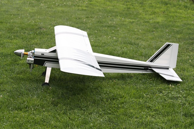

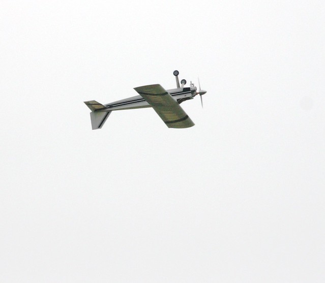
Despite its larger size, the Mentor-G has the traditional Basic Trainer appearance. Still, it is an attractive airplane whose steeply swept “windshield” gives it a racy look for a trainer.


The open, uncowled engine provides ready access for mixture settings and problem solving (if any should arise but none has so far). The Tru-Turn aluminum spinner was added for looks and nose weight but mostly to simplify starting with an electric starter. While the GF26i is designed for easy hand starting, I always prefer to use an electric starter. This is a personal choice as I value my fingers quite a lot.
While difficult to see in the photos, the Mentor-G uses two magnets to hold the front hatch in place. The hatch covers the forward fuel tank compartment. While convenient to use, this hatch can also cause a problem in outside maneuvers. I strongly suggest adding a single screw located between the magnets to hold the hatch in place. I’ll add a bit more on this later.
The GF26i engine started immediately and idled well from the start. Both the factory set high and low speed mixtures seemed perfect. But I did richen the high-speed mixture by about 1/16 turn as this was a brand new engine. I leaned it back to the factory setting after the first ten flights. The engined idled around 1000-1200 rpm with a top end around 7500 rpm using an APC 17 x 6 in. propeller. The regular gasoline was mixed 20:1 as per the instructions.

 The first takeoff was smooth and prompt after only about a 50 ft. ground roll. Watch a video of the Mentor take off and land below.
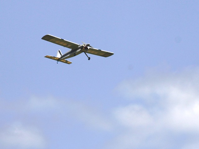
 Despite being a tail dragger, the Mentor-G surprised me by tracking fairly straight until the tail came up. It then required about 25% of the available rudder to track down the runway until flying speed was reached. Note the amount of right rudder in the photo above.
Then another pleasant surprise happened as the airplane needed no rudder at all in the climb. Maxford must have gotten the right thrust angle perfectly set for climbing. This is a help to new pilots as they start to master that left stick. The Mentor-G was able to hold a steady 30-degree climb angle after liftoff and gained altitude quickly but so fast as to worry a new pilot.
Despite being a tail dragger, the Mentor-G surprised me by tracking fairly straight until the tail came up. It then required about 25% of the available rudder to track down the runway until flying speed was reached. Note the amount of right rudder in the photo above.
Then another pleasant surprise happened as the airplane needed no rudder at all in the climb. Maxford must have gotten the right thrust angle perfectly set for climbing. This is a help to new pilots as they start to master that left stick. The Mentor-G was able to hold a steady 30-degree climb angle after liftoff and gained altitude quickly but so fast as to worry a new pilot.

 Another pleasant surprise was that the Mentor-G needed very little “up” elevator to maintain a level 30-40-degree banked turn. It should be easy for any new pilot to learn how to make level turns in this airplane. This was the first hint I had that the Mentor-G might have another mission in life in addition to teaching new pilots how to fly.
 As should any good Basic Trainer, the Mentor-G was proving to be an exceptionally easy airplane to fly. Its large size allows the pilot to easily and immediately see everything that is happening with and to the airplane. Because it is large, the airplane appears to perform in a stately manner and things appear to happen very slowly. There is plenty of time for a new pilot to think ahead of the airplane
The airplane cruised effortlessly at about 1/3 throttle without requiring any “up” trim to maintain level flight. Power addition did not change the pitch trim. Maxford got the down thrust angle as correct as they had the right thrust formula.
I was beginning to really like this airplane as a Basic Trainer. Its effortless slow flight, stable pitch trim, moderate control response (on low rates), easy turning ability, and stately airborne appearance make this an excellent Basic Trainer. But I was now slowly beginning to understand that there could be another mission, equally important, for this airplane.
As should any good Basic Trainer, the Mentor-G was proving to be an exceptionally easy airplane to fly. Its large size allows the pilot to easily and immediately see everything that is happening with and to the airplane. Because it is large, the airplane appears to perform in a stately manner and things appear to happen very slowly. There is plenty of time for a new pilot to think ahead of the airplane
The airplane cruised effortlessly at about 1/3 throttle without requiring any “up” trim to maintain level flight. Power addition did not change the pitch trim. Maxford got the down thrust angle as correct as they had the right thrust formula.
I was beginning to really like this airplane as a Basic Trainer. Its effortless slow flight, stable pitch trim, moderate control response (on low rates), easy turning ability, and stately airborne appearance make this an excellent Basic Trainer. But I was now slowly beginning to understand that there could be another mission, equally important, for this airplane.
 But its slow flight régime` had to be explored first before I could be sure. So the airplane was slowed way down until it stalled power off. This happened at an extremely slow airspeed. The stall was barely noticeable with little pitch down and recovery was immediate as soon as full “up” elevator was released.
I then held the Mentor-G in a series of deep stalls to see what would happen. After the first stall break, the full “up” elevator was not released. I held the airplane in the power off stall. What followed was a series of very shallow oscillations with no wing drop (laterally balanced remember?) or tendency to slip off to one side. Altitude loss was very gentle at no more than 500 ft. per minute (my guess) or about the same descent rate as used for landing the airplane.
The Mentor-G’s slow flight was fantastic in its gentle handling. This airplane’s power off slow flight abilities are on a par with the best trainers tested to date. The airplane will not snap roll or spin from the upright position no matter how the pilot tries to force it to do so.
But its slow flight régime` had to be explored first before I could be sure. So the airplane was slowed way down until it stalled power off. This happened at an extremely slow airspeed. The stall was barely noticeable with little pitch down and recovery was immediate as soon as full “up” elevator was released.
I then held the Mentor-G in a series of deep stalls to see what would happen. After the first stall break, the full “up” elevator was not released. I held the airplane in the power off stall. What followed was a series of very shallow oscillations with no wing drop (laterally balanced remember?) or tendency to slip off to one side. Altitude loss was very gentle at no more than 500 ft. per minute (my guess) or about the same descent rate as used for landing the airplane.
The Mentor-G’s slow flight was fantastic in its gentle handling. This airplane’s power off slow flight abilities are on a par with the best trainers tested to date. The airplane will not snap roll or spin from the upright position no matter how the pilot tries to force it to do so.
 So what about its power on slow flight? That was next. The Mentor-G was brought into the stall. About 1/3 throttle was slowly added to keep the airplane flying. I added “up” elevator to further slow the airplane while adding throttle to keep the airplane flying. It finally got to the point that the Mentor-G was nearly standing still in the air (had to be less than 10 mph) while maintaining altitude. There was no tendency to drop a wing, snap or do anything except fly straight ahead.
Forward flight speed was so slow that finally, the ailerons stopped working. The airplane had arrived at the point in its flight envelope where the ailerons had no effect on banking. Their only effect was to yaw the fuselage in the direction opposite the intended bank. What a perfect, real-life example of the effects of adverse yaw for any new pilot to witness first hand.
Yet, despite this silly slow airspeed, the Mentor-G was maintaining altitude. Of course, the rudder still had an immediate roll effect despite the slow airspeed should any correction be needed. The Mentor-G’s slow speed performance is very impressive. Only one other Basic Trainer even approached this performance and that airplane used speed brakes and leading edge slats on an over-sized wing as opposed to the Mentor-G’s clean wing.
So what about its power on slow flight? That was next. The Mentor-G was brought into the stall. About 1/3 throttle was slowly added to keep the airplane flying. I added “up” elevator to further slow the airplane while adding throttle to keep the airplane flying. It finally got to the point that the Mentor-G was nearly standing still in the air (had to be less than 10 mph) while maintaining altitude. There was no tendency to drop a wing, snap or do anything except fly straight ahead.
Forward flight speed was so slow that finally, the ailerons stopped working. The airplane had arrived at the point in its flight envelope where the ailerons had no effect on banking. Their only effect was to yaw the fuselage in the direction opposite the intended bank. What a perfect, real-life example of the effects of adverse yaw for any new pilot to witness first hand.
Yet, despite this silly slow airspeed, the Mentor-G was maintaining altitude. Of course, the rudder still had an immediate roll effect despite the slow airspeed should any correction be needed. The Mentor-G’s slow speed performance is very impressive. Only one other Basic Trainer even approached this performance and that airplane used speed brakes and leading edge slats on an over-sized wing as opposed to the Mentor-G’s clean wing.
 A Basic Trainer cannot live on gentle flight maneuvers alone. At an early point in the airplane’s training life, its pilot is going to want to try some basic aerobatics. A few loops serve as encouragement for the new pilot. Some rolls do the same and every pilot has to sometime learn that “up” elevator is “down” when inverted.


The airplane’s inverted performance is so impressive and unusual that the above photos are offered as a demonstration. The first photo above is a standard flight photo of a normal inverted pass. The photo to the right is an extreme enlargement of the elevator in the same photo (left). Note how little “down” elevator is needed for inverted flight.

 In fact, the Mentor-G’s surprisingly good inverted flight performance got me into trouble on that first flight from which the airplane itself had to save me. Everything was going so well that I pushed the airplane up into an outside loop.
The airplane performed flawlessly through the loop and afterwards. But, that magnetically held hatch popped off, allowing the ignition battery and all 14 ounces of nose weight fall out of the airplane. The engine quit just short of the outside loop’s quarter point when the ignition battery parted company.
There I was: Nearly flat on my back at low altitude and zero airspeed. Sounds like an old war story huh? Even worse, the airplane was now missing 19 ounces of nose weight. But the Mentor-G came through like a champ.
In fact, the Mentor-G’s surprisingly good inverted flight performance got me into trouble on that first flight from which the airplane itself had to save me. Everything was going so well that I pushed the airplane up into an outside loop.
The airplane performed flawlessly through the loop and afterwards. But, that magnetically held hatch popped off, allowing the ignition battery and all 14 ounces of nose weight fall out of the airplane. The engine quit just short of the outside loop’s quarter point when the ignition battery parted company.
There I was: Nearly flat on my back at low altitude and zero airspeed. Sounds like an old war story huh? Even worse, the airplane was now missing 19 ounces of nose weight. But the Mentor-G came through like a champ.

 It rolled over to upright and easily glided back to the runway. Its approach was tail low (note the lack of “up” elevator in left photo above) but rock steady. As the airplane slowed, it needed a little bit of “up” elevator to flare (photo above right). The landing was uneventful solely because this aircraft has such excellent slow flight handling. In a way, I was fortunate that the airplane was so good at slow flight that it had “tricked” me into exploring this flight régime` on the first flight. That is not my usual practice. Maybe the Mentor-G knew ahead of time that I was going to get “carried away” and into trouble?
In addition to its excellent handling, the Mentor-G proved to have a very wide CG range. But still be sure to set the CG at the 3 3/4 inch point as that is where it flies the best.
It rolled over to upright and easily glided back to the runway. Its approach was tail low (note the lack of “up” elevator in left photo above) but rock steady. As the airplane slowed, it needed a little bit of “up” elevator to flare (photo above right). The landing was uneventful solely because this aircraft has such excellent slow flight handling. In a way, I was fortunate that the airplane was so good at slow flight that it had “tricked” me into exploring this flight régime` on the first flight. That is not my usual practice. Maybe the Mentor-G knew ahead of time that I was going to get “carried away” and into trouble?
In addition to its excellent handling, the Mentor-G proved to have a very wide CG range. But still be sure to set the CG at the 3 3/4 inch point as that is where it flies the best.

 After a new hatch was made, held in place with screws, the airplane was flown for another 20 flights. Normal landings were easy to fly with approach speeds around 20 mph and power off touchdowns at less than 15 mph. It is possible to land this big airplane at much slower airspeeds using power but most new pilots will not start with this technique.
Later in their career, the Mentor-G will teach them to use power for altitude control and elevator to manage airspeed. This will be a required skill as the pilot ventures into more performance oriented aircraft and the Mentor-G will take them there.
The Mentor-G can also perform well, rolling with the best first airplanes and it will spin inverted. The roll rate can be quickened while stall turns are attractive. About the only performance that could be improved is the airplane’s slip characteristics. The rudder is small so the airplane cannot hold a truly noticeable slip for wind correction. The large ailerons too easily overpower the rudder in the slip. I suggest getting as much rudder throw as possible, at least 1 1/2 inch, when it becomes time to learn slip techniques (as every pilot must).
A NEW MISSION
After a new hatch was made, held in place with screws, the airplane was flown for another 20 flights. Normal landings were easy to fly with approach speeds around 20 mph and power off touchdowns at less than 15 mph. It is possible to land this big airplane at much slower airspeeds using power but most new pilots will not start with this technique.
Later in their career, the Mentor-G will teach them to use power for altitude control and elevator to manage airspeed. This will be a required skill as the pilot ventures into more performance oriented aircraft and the Mentor-G will take them there.
The Mentor-G can also perform well, rolling with the best first airplanes and it will spin inverted. The roll rate can be quickened while stall turns are attractive. About the only performance that could be improved is the airplane’s slip characteristics. The rudder is small so the airplane cannot hold a truly noticeable slip for wind correction. The large ailerons too easily overpower the rudder in the slip. I suggest getting as much rudder throw as possible, at least 1 1/2 inch, when it becomes time to learn slip techniques (as every pilot must).
A NEW MISSION
But the Mentor-G is ideally suited to a second mission in life. Here is an airplane that flies slowly, stays nearly level in a turn, is extremely forgiving, is easy to see in the air, can operate out of the smallest airfields and burns economical gasoline. Well, economical when compared to glow fuel.
It can stay airborne for about 15-17 minutes, with reserves, and even longer when a larger fuel tank is installed (there’s plenty of room for it). Put all these pluses together and I believe that the Mentor-G is just about the perfect airplane that clubs can use to expose the public to RC flying through TAG-like programs. So many clubs these days now invite the public to “come fly our airplanes” (dual controls of course) that this mission has grown in importance.
The Mentor-G has to be one of the best airplanes available to introduce non-flyers to the wonder and satisfaction of RC flying. Its extremely economical price of $400 with engine and fast 20-hour assembly makes it a perfect club trainer.

 Its special flight characteristics, especially the ability to make nearly level turns, means that even non-pilots will be able to fly it around that race-track pattern with little trouble. The first photo above shows the Mentor-G completing a level 180-degree turn, just at the point of rolling out of it. The right photo above is the extreme enlargement of the tail section in the first photo. Look, almost no “up” elevator was used throughout the turn. You just can’t get any better than this for experiencing RC flight.
SUMMARY
Its special flight characteristics, especially the ability to make nearly level turns, means that even non-pilots will be able to fly it around that race-track pattern with little trouble. The first photo above shows the Mentor-G completing a level 180-degree turn, just at the point of rolling out of it. The right photo above is the extreme enlargement of the tail section in the first photo. Look, almost no “up” elevator was used throughout the turn. You just can’t get any better than this for experiencing RC flight.
SUMMARY
This airplane is so surprisingly good as a Basic Trainer that it also becomes one of the best TAG airplanes. But since it burns gasoline instead of glow fuel and has far more staying power than e-powered trainers, it might just be the best all-around trainer and TAG airplane there is. It can also get pretty exciting when pushed, especially with its surprising inverted and roll performances.
For more information on this very special Basic Trainer, go to: http://www.maxfordusa.com/mentor-g26cctrainer.aspx
Image

Related Content
The EnterTrainer
Image

Written and designed by Fred Randall Online exclusive plans-build article. Download the entire plans for free. I am not an accomplished RC pilot. My hands shake and my knees want to buckle whenever I
Looks Like A Warbird And Flies Like A Trainer
Image

Written by Terry Dunn Review As seen in the March 2021 issue of Model Aviation. Bonus Video At a Glance Specifications Type: Foam warbird ARF Wingspan: 47.2 inches Wing area: 389 sq. in. Length: 39.4
Great Planes Avistar GP/EP Sport Trainer
Image

Written by Greg Gimlick A Giant Scale Sport ARF Product Review Photos by the author As seen in the March 2016 issue of Model Aviation. Specifications • Model type: Giant Scale sport ARF • Skill level


Comments
Mentor-G
I want one.
Maxford USA Mentor-G
My next plane!
Add new comment