Building has always been a big part of the hobby for me, and like many other modelers, building a rubber-powered Free Flight model was often a first experience. Companies such as Guillow’s, Keil Kraft, Sterling, and Skyleada helped shape untold numbers of modelers, as well as full-scale pilots.
Comet Models was another company that produced an impressive number of designs in a variety of sizes and aircraft types. Unfortunately, many of these companies, including Comet, no longer offer kits; however, many of their plans can now be found online.
Having built a fair share of aircraft from these foundational modeling companies when I was younger, one thing always popped into my head: If only I had RC gear small enough to convert this model to RC. Fortunately, that size of radio gear is not only available today but quite economical. Wanting to explore this option, I found a set of plans that really looked great: Comet’s P-40C with an 18-inch wingspan.
Using the plans as a foundation, I redesigned the model for RC with a 27.25-inch wingspan, featuring four channels. It uses an 18- to 24-gram motor and is powered by a 2S LiPo pack. The design in this article is the fourth update from the original version, so I am considering this to be a "Comet-inspired" model. I also created a video build series. The link is in the "Sources" list.
02. The tail feathers are framed up and hinged.03. The fuselage is started with the keels and left formers halves added. The author is beginning to add the 3/32-inch square stringers.04. Chin stringers have been added with the piggyback pieces, as described in the text.05. The piggyback stringers are shaped with the motor mount in place, along with the ducting.
The P-40, in all of its versions, is one of the most recognizable aircraft of World War II, and was often considered a "stopgap" until better aircraft were introduced. History has often considered it a second-class fighter, something that I think is unfair. The P-40 was quite agile, with more recent claims that it’s comparable—if not better than—the Mustang or some versions of the Me-109 in maneuverability at certain altitudes.
It was designed for low- to mid-altitude fighting, and in these areas, it fared well. It was rugged and could withstand a lot of damage, certainly allowing many pilots to return home with damage that would have downed their opponents. The warbird could dish it out as well. Some versions had four .50-caliber guns, while most carried six.
The P-40 served on all of the major fronts and earned a dependable reputation. The most famous of all P-40 squadrons was the American Volunteer Group (AVG), better known as the Flying Tigers. They predominantly flew the early versions of the P-40 (B and C models) against nimble Japanese aircraft (including Nates and Oscars). Using the P-40’s strengths, the AVG pilots were able to achieve a kill ratio of at least 10 to 1; however, there are arguments that it was actually higher.
The model’s construction is conventional, with the fuselage built on a left/right keel and the wing in three sections—all on top of the full-size plans. The main construction material is 3/32 balsa, with some additional 1/16- and 1/4-inch balsa needed. There is also a small amount of 1/8-inch light plywood used.
Similar to some of my other designs, the canopy is made from clear, flat sheet. There is an option for plug-in landing gear, and templates to print your own tissue covering. The plans are available as a free download at www.ModelAviation.com. Manzano Laser Works offers a short kit if you do not want to hand cut the parts, and Rabid Models offers a spinner specifically made for this model. Both are listed in "Sources."
I like to start with the tail sections first. Find all of the H parts and set them in place on top of the plans. Use pins between H5 and H6 for spacing. When satis fled, glue everything in place. Add the 3/32-inch square stringers and bend the U-shaped 1/32 wire to connect the two elevator halves.
Sand the assembly and set it aside. Pin the V parts to the board. Note that V5 is later cut along a marked line to separate the vertical from the rudder. If you are only going with elevator and aileron controls, you can leave them together. With the vertical/rudder sanded, hinge the model according to your preference. I like to use CA hinges.
Moving on to the fuselage, pin all of the K parts on the board, noting the scrap 3/32 stringer on K4 and between K1 and K8, and glue them all in place. Glue sub-formers K4B and K7B to their main former according to the plans. Review the plans’ detail for F2 and mark the former if you intend to use a three-blade propeller.
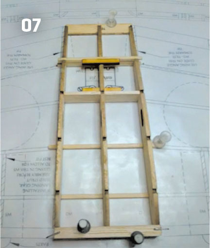
06. The hatch rails are blended into the fuselage and the hatch is cut free.07. This shows the start of the wing’s center section.08. The LE, WOJ, and TE2 assembly are in place. Note the pins that are used for spacing.09. TE3, the ribs, stringers, and ALE have been added. Note that the outermost rib (W8) is sitting on WOJ.
Add formers F1 to F9 to the keel, making sure that they are 90° to the building board. Add all but the topmost stringer forward of F6. This will be added later when finishing the hatch. The stringers beneath the "chin" of the model are best added with the piggyback method. This is done by adding a scrap stringer (slightly taller but still 3/32-inch thick) that is notched into F2 and butts against F3 right under the notch. The main stringer is then glued on top of the scrap balsa, piggybacking it.
When this is dry, plane and sand the lamination to match the correct curve and be flush with F2 (there is also a detail on the plans to show this process). This reduces the stress on the airframe and does not impact the strength of the model. Add the wing saddle (WS) and the lower hatch rail from 3/32 × 1/4-balsa cut to length. Remove the fuselage from the board, adding the other former halves.
Add the cardstock ducting (see template sheet) before adding the other stringers, WS, and the lower hatch rail. Add a 3/32 × 1/8-inch round magnet to formers F4, F4A, F6, and F6A per the cutout holes. Use clear tape to protect the lower hatch rail and F4 and F6. Set F4A and F6A in place, minding the magnet polarity, and add the upper hatch rail.
Glue the upper hatch rail to F4A, the upper part of F5, and F6A. Using the plans as a template, cut a stringer from 3/32-inch balsa and use it to connect F5A and F6A. Add the top forward stringers. Remove the tape and blend the sides of the hatch rails to match the fuselage’s contour.
When you are satisfied with the sanding, cut the hatch free. Add the 1/16-inch balsa cross decking according to the plans and remove the scrap stringer between K1 and K8. Test-mount the motor and ESC, shimming the motor as needed. I found that 1.5° to 2° of right thrust works well if you are using a three-blade propeller. If you are planning on "belly flopping" into grass, use scrap 3/32-inch balsa to infill between the bottom stringers between F2 and F4, ending roughly 1 inch before F4. The gap will be left uncovered and will be the air exit from the ducting. Add K3A in place and test-fit the tail section, but do not glue it at this time.
The wing has several subassemblies before the main construction. If you are adding the plug-in gear, make the W3 lamination and test-fit the square brass tubing, but do not glue it yet. Glue three washout jigs (WOJ) together and glue trailing edge (TE) 2 and TE2A together. Cut the three sections of leading edge (LE) from 1/4-inch balsa, using the template provided on the plans. Tack-glue the tip-angle guide (TAG) to TE3. Starting with the center section, pin the LE and TE1 to the board. Position W1 and two W2s in place. Make sure it is 90° to the board then glue in place. Test-fit the servo mounts and glue them in place. Test-fit and mount the rudder and elevator servos and remove them when done. Add the top and bottom 3/32-inch square stringers.
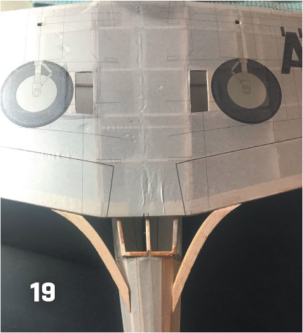
10. All of the ribs have been added. The rib farthest to the right (W2) will be angled outward using the wing-angle guide.11. The servo, top stringers, and the aileron ribs have been added. Note that the top stringers do not go all the way to the tip of TE3.12. The control rods, made from .032-inch wire, are kept from flexing by boxing them in with scrap stringers.13. This shows some of the printed tissue sheets. These are attached to legal sheets for printing.14. The initial prototype is ready to be covered. The paper canopy was printed to test-fit it before making the clear version.15. The interior canopy framing is printed and the inner panels have been cut free.16. The exterior canopy framing is attached to the back of the interior before removing the panels. Here, the panels have been glued to the 3-mil clear plastic sheet. See the additional instructions for the AVG livery.17. The front windscreen is attached first at the center from top to bottom. After it is dry, the sides are glued.18. The completed forward canopy parts are all attached with PVA or canopy glue.19. The wing has been attached and now the balsa wing fillet parts are added. These are covered top and bottom with cardstock fillets.
Starting with the right panel, pin the LE, stringer 1, and WOJ in place over the plans and place tape on top of WOJ to prevent it from being glued to the wing. Place pins between stringer 4 and ALE, and just left of W6 in the aileron bay. Set the TE2 assembly and TE3 in place over WOJ.
Glue TE2, TE3, stringer 1, and LE together. Pin TE2 to the board just inside of W6 according to the plans. Set W8 in place. The rear will be elevated by WOJ, creating the washout. Glue to TE2, TE3, stringer 1, and LE. Set stringers 2 through 4 over the plans and test-fit W6 and W7. Glue W6 in place and the remaining stringers to W8.
When it is dry, glue in W7. Test-fit ALE and glue it in place. Glue W5 through W3 in place, making sure that they are 90° to the board. Rib W2 is tilted toward the wingtip. Use the wing-angle guide to set the angle. Add a scrap piece of 1/16-inch balsa for the servo-mounting plate. The aileron servos are glued to the wing, so be sure to test them thoroughly before mounting them according to the plans.
Add the top stringers at this time. Note that they will need to be beveled to match the TE3 angle and might not go all the way to the outer edge of TE3. Make the aileron ribs from scrap 3/32-inch balsa and sand them to match the other rib sections. Remove the wing panel from the board and trim the LE and remove the TAG.
Using the templates, shape the LE. I like to use a small plane to take off the majority then a sanding block for final shaping. Sand the overall panel, including the TEs and wingtip. Cut the aileron free and in-fill with scrap between the top and bottom stringer 4 in the aileron bay. This will be the hinge-mounting point.
Hinge the ailerons, but do not glue them in yet. Build the left panel the same as the right. Pin the center section in place over the plans. Set the left and right panels in place, lifting the wingtips up 1.25 inch at W8. Glue the outer panels to the center panel. Additional stringers tying the outer panels to the center one can be added. These were not needed on the prototype, but if a more powerful motor is used, I recommend it.
20. This is a top view of the finished prototype model.
Test-fit and tape all of the main parts together. Mount the motor, ESC, and the elevator/rudder servos. Du-Bro micro control horns and EZ connectors were used. Run the pushrods from these servos to the control horns on the rudder and elevator. Use scrap to make their exit points and scrap stringers on F7 and F8 to "box in" the wire. The wire used was .032 diameter, and with the stringers added. No tubing or sleeve was needed.
Test the balance point of the airframe according to the plans. Move the battery pack as needed to try to eliminate the need for additional ballast.
The model can be covered with lightweight film, but the prototype was covered in printed tissue. Along with the plans, tissue templates for two versions (Flying Tigers and silver) and a detailed cockpit are available for download. Printing your own tissue is a fun process and can really dress up your model.
The canopy is made from paper. Thin, clear 3-mil plastic was used on the prototype. Print out the templates on paper. For the silver livery, there is also an option to print the frames onto the tissue.
Cut along the outside box, fold along the dashed line, and glue. Cut out the interior window panels then glue the main sections (interior side down) to the clear plastic. When dry, trim around the outside of each of the three main panels. Glue the front windscreen first, followed by gluing the center canopy to the hatch. The rear canopy is done the same way and glued to the main fuselage. After all is covered, test-fit the wing and tail and glue it after it is aligned.
Add the balsa wing-fillet parts according to the plans. Use the templates to make the top and bottom fillet parts from light cardstock. Make the belly pan and gear pods then cover and attach them. The larger, square brass tubing can now be added. Glue in the hinges and control surfaces, connecting them to their servos.
Set the throws to be plus or minus 1/2 inch for the elevator, plus or minus 3/8 inch for the ailerons, and plus or minus 3/4 inch for the rudder. A 450 mAh 2S battery provides 4 to 5 minutes of flight. Double-check the balance according to the plans. The model can be flown with the gear attached (and retainer tabs used) or can be hand-launched and landed on its belly.
21. A close-up of the canopy and details. Patterns for a seat, cockpit tub, rear interior, and instrument panel are included in the templates.22. A strafing run at the park field.
The power setup provides a nice envelope for maneuvers. Loops, rolls, stall turns, and Lazy 8s are all possible, but you might want to increase the throw slightly if you are doing more dynamic maneuvers. Stalls are standard in recovery, thanks to the Clark Y airfoil and the washout. Landings are standard; just keep some power on until nearly ready to touch down.
Building stick-and-tissue models is a lot of fun with off-the-shelf electronics. It can open up a new world for these designs. Give the park flyer P-40C a try. I hope it will inspire you as well. Just be sure to keep your six clear from any park flyer Nates!
01. The plans show templates for the top intake and gun pods. You can also see the cardstock main fillets.
By Derek Micko | [email protected]SOURCES:Model Aviation onlinewww.ModelAviation.comManzano Laser Workswww.manzanolaser.comRabid Modelswww.rabidmodels.comFlying The Fun Scale Models P-40C In The Parkwww.youtube.com/watch?v=yr2bzeunf74


Comments
Build series of the P-40C Park Flyer
For those interested in a video build series for the model, it can be found here:
https://www.youtube.com/watch?v=y-UxXIluFd0&list=PLSc5DLNcrz4thnJ2bhqlu…
or search YouTube under "Fun Scale Models"
P-40
Hoping to build it.
Add new comment