Last year, Paul Kohlmann and I built park flyer versions for our "Fighter Face-Off" series that appeared in the September through November 2021 issues of Model Aviation. The models featured were a Brewster Buffalo and a Nakajima Nate, both with 30-inch wingspans.
After finalizing the Nate design, I wanted to build another park flyer model. These smaller models are less complex and can be built quicker than larger ones. Their size also allows you to toss them fully assembled into your vehicle, head to a park, install the battery, and fly. Wanting to keep with a less-modeled aircraft, I decided on the Bell P-63 Kingcobra.
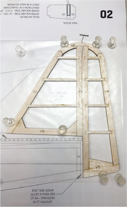
01. The horizontal stabilizer is built over the plans.02. The vertical stabilizer has six parts.03. The keel is pinned to the board.
The Bell Aircraft Corporation was a company known for its unique designs. From its first military design, the Airacuda, to the early X Plane series, the company’s designs pushed the limits of technology in the day. The forerunner to the Kingcobra was the P-39 Aircobra, an aircraft that was unique in that the engine was mounted behind the pilot, allowing a 37mm cannon to fire through the propeller hub.
The aircraft also featured a nose gear, something uncommon for single-engine fighters at the time. However, the promising P-39 did not live up to expectations when armor and armament were added, and it was not long before an improved version was needed. The result was the P-63 Kingcobra. Although the P-63 resembled a larger version of the P-39, it was an entirely new design. The aircraft featured a supercharger, laminar airfoil cross-section, and an improved engine.
The prototype first flew on December 7, 1942. Although the resulting aircraft was a significant improvement over the P-39, the U.S. Army declined larger orders because the P-51 was still considered a better aircraft. However, the Russian Air Force was interested in the P-63 and much of the production run was sold under lend-lease.
Of interesting note, while not accepted at first, Bell engineers eventually took a lot of feedback from the Russian pilots to improve later versions of the P-63. The Kingcobra gained notoriety after the war in the late 1940s in the Reno Air Races, where they were modified and appeared with more clipped wings. The ultimate was the Tucker Special, with nearly 13 feet of wing removed to help reduce drag.
The Model
The model’s construction is straightforward. The fuselage is built in halves (left and right) over a keel and the wing is built in three sections flat on the board. The main material used is 3/32-inch balsa, but there is some 1/18-inch light plywood and 1/4- and 1/16-inch balsa. There is an option to employ "plug-in" landing gear or a modeler can omit this for an even lighter version.The prototype model is powered by a 24- to 30-gram motor and features a four-blade propeller. There is also a 3D-printed spinner from Rabid Models. Information about the motor, propeller, and spinner is in the "Sources" listing. The plans show all of the templates needed to build the model, but if a modeler wants to save time, a short kit is available from Manzano Laser Works.
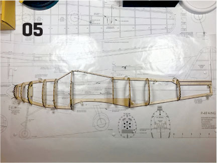
04, 05. Sub-formers are added to F5 and F7 and all of the lefthand formers have been added.04, 05. Sub-formers are added to F5 and F7 and all of the lefthand formers have been added.06. Stringers featuring the "piggyback" method are started.07. The propeller and 3D-printed spinner are mounted to the motor.08. Ducting is made from heavy paper.09. This shows the hatch rails and canopy frame parts.10. The LEs and TEs are glued and elevated with the WOJ.11. This is the angle guide for W1 to set the dihedral angle.12. All of the stringers are in place.13. Remove the notched section on the ribs for the ALE.
The aircraft weighs between 7 and 9 ounces. The airframe is 59 grams, so with a little modification, it could be converted to Free Flight. Additional features include patterns to print on tissue to cover the model. The canopy can be made from flat, plastic sheet and paper, and there is also an option to make a detailed cockpit from cardstock. If you are looking for additional building information, I have created a couple of build videos for this model, so whether you cut your own parts or get the laser-cut short kit, let’s get to building!
The Build
Start with the tail sections. These are made from 3/32-inch balsa—both the shaped parts, as well as the stringers. Both H3 and V3 are later separated to make the rear of the horizontal and vertical stabilizers and the elevators and rudders. The elevator halves are connected with 1/32-inch wire bent into a U shape. After it is complete and sanded, hinge with your choice of hinges. I used CA hinges on the prototype.
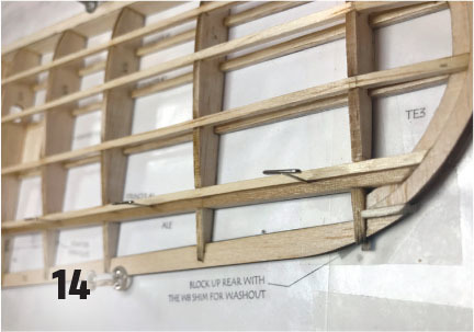
14. This shows the ALE installed.15. The battery in the rear hatch can be moved fore and aft for balancing.
The fuselage has seven keel sections. Pin and glue these over the plans after protecting the plans with waxed paper or thin, clear plastic film. Add a scrap piece of 3/32-inch stringer at the rear edge of K4. All of the stringers will butt against this.
Add the sub-formers to F6 and F8 and add scrap 3/32 to F2, according to the plans. Starting with F10, set all of the formers in place and glue them at 90° to the board. Start the stringers by adding stringer #5 (see the plans details) from F10 to F1. Because the P-63’s nose comes to a fine point, there is a sharp curve between F1 and F2.
One option is to steam or use window cleaner with ammonia to help form the curve. The other is what I call the "piggyback stringer" method. This is done by adding a scrap stringer that is notched into F1 and butts against F2 beneath the notch. The main stringer then is glued on top of the scrap, piggybacking it.
When the assembly has dried, plane and sand the lamination to match the correct curve and be flush with F1. (Details on the plans show this process). This reduces the stress on the airframe and does not impact the model strength. If employing the plug-in landing gear, add the brass tubing and G parts, as shown on the plans.
Make the lower hatch rail from 3/32 × 1/4-inch balsa cut to length and install, as shown on the plans. Add the remaining stringers. Wet the outside of the wing saddles with window-cleaning spray and glue them in place. Remove the left half of the fuselage from the board.
Before adding the other half, mount the spinner and propeller to the motor to test the spacing between the backplate and F1. You might need to move F3A in front or behind F3 to achieve the correct spacing. Also, if you are using the four-blade propeller, see the plans because you will need to mount the motor off-center to employ the right thrust that is needed. If using a two-blade propeller, this is not required.
Remove the ducting cutouts on F3 through F5 and make the ducting from heavy paper, using the provided template. Test-fit the ducting and sand and trim the cutouts to make sure it’s a good fit before gluing in place. Air intakes will be added later, and the air will exit between the bottom stringers in front of F6. Add the other half of the formers and stringers at this time, adding the 3/32 × 1/8 magnets in F5 and F7. Also remove the premarked and precut sections on F4 through F7.
Use clear tape to cover the top of the lower hatch railand the hatch-facing sides of F5 and F7. Add the magnets to F5A and F7A and set in place along with the upper hatch rail. Add F6-1, K2, F6B, and F6C in place, along with the 1/16-square stingers and glue when fitted. Remove the tape and blend the two hatch rails to match the fuselage side contour. Add the 1/16-inch crossgrained balsa sheet between F5 and F7, sitting on top of the #6 stringer. Sand the fuselage and set it aside.
16. Cockpit templates are available to be printed on heavy paper.17. The flat-sheet canopy is 3 mil plastic with paper frames. The template is included with the plans.18. The completed canopy is glued to the hatch/canopy frame.19. Cardstock intakes provide motor cooling.
Prepare for the wing by cutting the leading edge (LE) from 1/4-inch balsa using the templates on the plans. Starting with the center section, pin the LE and trailing edge (TE1) in place, adding the bottom stringers and the three W1s. Make sure that they are 90° to the board before gluing them in place. Add the top stringers and the 1/16-inch balsa in-fill sheeting on the top, as shown on the plans. Sand the top of the LE to match the airfoil but just round the bottom in the center section.
Starting on the right outer wing panel, glue TE3 and TE4 on top of each other, glue the two washout jigs (WOJ) together and, if adding plug-in gear, the W3 assembly. Pin the LE, TE2, and the TE3/4 assembly in place and glue all of them together. When dry, unpin the wingtip area and slide WOJ in place over W8 and under the TE, using use clear tape to hold it in place and prevent gluing it to the wing.
Place a pushpin in place on the outside of W6. This and the WOJ will build the correct amount of washout into the wing. Set the rearmost bottom stringer (#4) in place. This sits on top of the WOJ and butts against TE3. Test-fit the W3 assembly, W5, and W8 in place. Slide the other three bottom stringers in place and when you are satisfied with the fit, glue all of these parts in place. Add all of the remaining ribs (except W1) and add the scrap 1/16-inch servo plate, according to the plans.
Use the outer W1 angle guide to set the correct angle for the dihedral. The rib should tilt toward the wingtip. Add the top stringers. (These sit on top of TE3 and butt against TE4 at the wingtip.) Add pins directly behind stringer #4 (top and bottom) in the aileron section and on the outside of W4. I’ve found that 1-inch T-pins are prefect for maintaining the 1/32-inch gap that is needed.
Cut out the notched sections on ribs W5 through W7 and test-fit the aileron LE (ALE), along with W4A and W8A. Glue it when the fit is correct.
Thoroughly test your servo before gluing it to the 1/16-inch plate. A 4.3-gram servo was used on the prototype in each panel. Remove the panel from the board and shape the LE using the templates. A small block plane will dramatically help shorten this process. Sand the wingtips and TE before cutting the aileron free.
In-fill between the #4 stringers (top and bottom) with 3/32-inch balsa scrap in the aileron section. Sand the ends of the aileron and mark the location for the hinges on the wing TEs and the aileron LE. I used CA hinges. Sand a curve to the aileron LE. Build the left half of the wing the same way as the right. With the center section pinned to the board, set an outer panel in place, sanding the W1s to make a flush fit. Prop up the outer panel 1.45 inch at W8 and glue it to the center section. Repeat the same for the other panel.
Test-fit and tape all of the model parts together with the motor, propeller, and spinner mounted. This is a great time to make "airplane noises." (Try not to let others see/hear this because they will probably not understand.) It’s also a good time to check the balance point. Because the full-scale aircraft was mid-engined, having the motor in a long nose can make the airplane nose-heavy.
20. Plastic retaining clips are necessary if choosing to fly with the gear. Air exit holes are placed slightly in front of the wing. long nose can make the airplane nose-heavy.
The prototype needed an additional hatch to mount the battery between F9 and F10. Depending on your motor/propeller/spinner combination, you might be able to mount the battery in the rear of the canopy hatch. If this is not far enough aft, you will need to perform the next steps to make the bottom rear hatch.
For this hatch, cut K5 and stringers #7 through #9 between F9 and F10. Set these aside for now. Add additional scrap stringers to the inside edge of stringer #6 between the formers to make a hatch rail. Add magnets to F9, F9A, F10, and F10A. Use clear tape as you did when creating the canopy hatch. Set the 3/32 × 1/4-inch hatch rail and F9A and F10A in place, minding the polarity of the magnets.
Add the previously cut stringers and section of K5 to F9A and F10A. Add the 1/16-inch cross-grained balsa between F8 and F10 sitting on the bottom of stringer #3. This will be the battery mounting plate. Sand the hatch for the best fit.
With the battery mounted in the canopy or rear hatch, test the rest of the radio gear for the best balance location. By moving the battery fore or aft in the respective area, you might not need to add any ballast. The ESC sits behind the motor between F3 and F5.
On the prototype, the elevator and rudder servos are in the rear hatch area on either side of the battery, but these can also be located in the canopy hatch area, as shown on the plans. The receiver can be placed where it fits best. The prototype has it slightly forward of F7.
The model can be covered in lightweight film, but on the prototype, the aircraft was covered with printed tissue. There are templates provided with the plans if you wish to go this route, and there is a link to a video showing how to print and apply the tissue. With either option, keep the finish as lightweight as possible for a better-flying model.
If you have the interest and the equipment, there are templates provided to print a detailed cockpit that really dresses up the airplane—including a profile pilot.
Make the intake from the IN parts and attach, according to the plans. The covering is removed between F1 and F2 stringers #5 and #6 for the intake ducting made from cardstock.
The wing fillets are also made from cardstock using provided patterns. The model features a canopy made from 3 mil flat, clear sheet with paper framing. Follow the instructions and gluing order and it will result in a neat, retro look for the model. A commercial military canopy can also be used. Bend the landing gear (if being used), according to the plans templates. Balance the model 1.5 to 1.75 inches from the center section LE. Add other details of your preference. Extras really make the model shine.
Flying
Set your control throws to be plus-1/4 inch for the elevator and ailerons and plus-3/8 inch for the rudder. If using a four-blade propeller, a 1/32-inch shim behind the motor mount will give the necessary 1.5° to 2° right thrust.
The prototype weighed slightly more than 8 ounces with the gear and a 2S 450 mAh battery pack. This provides 4- to 5-minute flights with good throttle management. The model has been flown from a paved surface with the gear mounted and held in place with tabs (see the plans detail), but it really comes alive when flown from grass with the gear removed. Speed is not over the top, but it has a nice, realistic look. Loops, rolls, and basic maneuvers are possible but might require more control throws. Stalls are straightforward because of the washout, and recovery is normal. Approaches are also normal. Slowly reduce power until flair, and then land.
The park-flyer-size P-63 is a lot of fun to build, as well as fly. It grabs a fair amount of attention at the field. The prototype livery is a faux racing scheme, but the templates allow you to add other details if you chose. Give the flatsheet canopy and printed tissue a try. The results are very satisfying.
SOURCES:Manzano Laser Workswww.manzanolaser.comRabid Modelswww.rabidmodels.comFun Scale Models YouTube Pagehttps://bit.ly/32ga3usFun Scale Models P-63 Kingcobra in flighthttps://youtu.be/Dpf9ZYHxXG0FSM Printing on Tissue Ki27 Natehttps://youtu.be/0980sL-UjC0Park Flyer Fighter Face-Offwww.ModelAviation.com/fighter-faceoff-park321–23. The model can be covered in lightweight film, but the prototype aircraft was covered with printed tissue. There are templates provided with the plans if you wish to go this route and there is a link to a video showing how to print and apply the tissue.21–23. The model can be covered in lightweight film, but the prototype aircraft was covered with printed tissue. There are templates provided with the plans if you wish to go this route and there is a link to a video showing how to print and apply the tissue.21–23. The model can be covered in lightweight film, but the prototype aircraft was covered with printed tissue. There are templates provided with the plans if you wish to go this route and there is a link to a video showing how to print and apply the tissue.
Few aircraft have a more distinctive shape than the Chance Vought F4U Corsair. It featured an iconic inverted gull-wing design, a massive three- or four-blade propeller, and a long nose. It was a welcome sight to Allied forces, and its characteristic whistle struck fear in its opponents.
Written by Paul Kohlmann and Derek Micko Scratch-building and flying opposing aircraft, Part 2 As seen in the October 2021 issue of Model Aviation. Order Plans from AMA Plans Service DOWNLOAD FREE
Written by Paul Kohlmann and Derek Micko Scratch-building and flying opposing aircraft As seen in the September 2021 issue of Model Aviation. Order Plans from AMA Plans Service DOWNLOAD FREE PLANS
Nice job on the P-63.
I have downloaded your plans and plan on building the '63 before it gets too warm here in Florida.
I have been wanting to build a P-39 Aircobra for some time now. It is my favorite plane. You see, my Father worked for Bell Aircraft in Niagara Falls NY from the late 30's until he retired in 1965. He built P-39's, P-63's and worked on some of the X planes.
After I build the Kingcobra I'm going to try my hand at designing and building the Aircobra.


Comments
P-63
Nice job on the P-63.
I have downloaded your plans and plan on building the '63 before it gets too warm here in Florida.
I have been wanting to build a P-39 Aircobra for some time now. It is my favorite plane. You see, my Father worked for Bell Aircraft in Niagara Falls NY from the late 30's until he retired in 1965. He built P-39's, P-63's and worked on some of the X planes.
After I build the Kingcobra I'm going to try my hand at designing and building the Aircobra.
Thank you for a great design of the P-63.
Add new comment