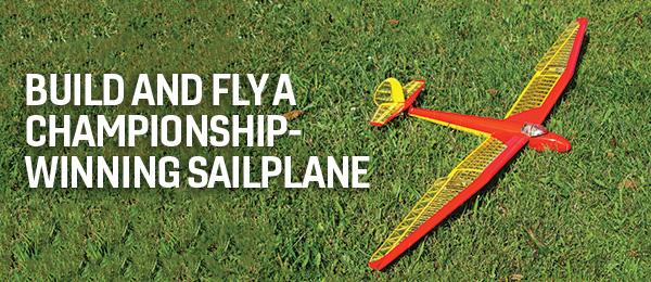
Add this distinctive glider to your collection of aircraft
By Fitz Walker | [email protected]
As seen in the April 2023 issue of Model Aviation.
FIRST FLOWN IN 1935, the Göppingen Gö 3 Minimoa is a distinctive glider, but not just in looks. It had quite a few advanced design features that were new to sailplanes at the time—swept outer wingtips, differential aileron controls, a wheel with brakes, and the first use of water ballast.
Almost immediately, it won glider competitions and set altitude records. It is even said that the distinctive gull wing was formed by bending a straight spar using water!
Hobby Club is offering a faithful model kit of the Minimoa with a 112-inch wingspan. This is an all-balsa-and-plywood laser-cut kit that includes parts for functional spoilers and has a provision for an optional electric motor in the nose.
The kit has an extensive number of laser-cut wood sheets. Most are 1.5mm- and 2mm-thick balsa, with some 5mm balsa and 2mm plywood. Nearly every piece of wood you will use in construction is laser-cut to shape, with the main exception being stringers and capstrip lengths. The intricately cut wing ribs are mostly balsa, with some plywood ribs in high-stress areas.
The manual is large, with 130 pages of mostly color photos that needed to be downloaded as a PDF file from the Hobby Club website. I had to print it, but it was handy to be able to zoom in on the construction photos for picking out the finer details because the manual has few words. What it lacks in words is made up by the extensive number of build pictures contained within.
Plans come in two large, folded sheets for the wing and fuselage/tail. They are relatively clear, but are mostly useful for aligning the parts because the specific part details are in the manual. Several bags of screws, nuts, and hinges are included, along with the center wheel.
The wood quality is quite good. The crisp laser-cutting caused several parts to become loose in the box, having fallen from their respective wood sheets.
A total of 51 balsa sheets and 11 plywood sheets of laser-cut parts comprise the kit. Fortunately, there is a parts guide at the end of the manual to help locate specific parts.
Building
Construction starts with the rudder. This is where the parts index in the manual starts to be appreciated because pieces are spread out over several different wood sheets and are conveniently labeled. The parts fit was good and I was able to assemble a large section in my hand without the use of the plans. The tip and base of the rudder will need to be sanded to shape from the 5mm thick, stacked, laser-cut parts.
This shows all of the parts that are included in the kit.
The horizontal tail is built up and partially sheeted with additional capstrips, so expect to spend some time building it. Fortunately, even the capstrips for the ribs are laser-cut. My hobby knife had less of a workout than I had expected. Well, almost … There was a small tip piece that I either misplaced or was not cut out, but I easily "cloned" it from another part.
The built-up tail was just a warm-up for the wing, which is an order of magnitude more intricate and has ribs that look as though they were shrunk from a full-scale aircraft.
It pays to really study the instructions closely. Some details might not be obvious at first glance or may only be apparent if you look a few steps ahead.
The wing is built in two sections for each side over the plans using pins and weights to keep everything aligned and in place. The wing construction is a basic D-tube with a secondary spar near the trailing edge. Outer wing panels have clever triangulated wing spars that tab together at the wingtips.
The wing and spoiler are detailed in this photo. Note the intricate details of the wing ribs.
All of the wing sheeting is laser-cut in multiple sections that fit together like a puzzle. Wing ribs in the wing centers are balsa, while the outer portions are light plywood. Each rib also keys into slots on the spars, making for easy alignment. These ribs start to get small and quite delicate for the outer wing panels. I had to repair several after damaging them either in the sheeting process or final sanding.
I did have a couple of nitpicks on the construction of the outer panels. For starters, part of the tip wing sheeting assembly didn’t quite align correctly and needed some extra trimming.
Secondly, a section of leading edge at the tips is made from square stock that must be split lengthwise into triangle stock. It’s not hard to do, but it is tricky to do well. Sheeting the outer panels also required applying window cleaner to the wood to make it easier to bend the sheeting over the curves.
The aileron servos are also located in the outer panels beneath the flushmounted access hatches. When basic construction of the wing panels is done, the spoilers and their servos are installed. Space limitations require submicro servos—in my case, Hitec HS-65s. The spoilers themselves are 1.5mm thick plywood and are attached to hinges with screws. This allows them to be easily removed for servicing the servos.
The fuselage is built in two halves on the plans. Care must be taken to identify the tops of the ribs because they are not symmetrical.
The rear of the fuselage is built over the plans in two halves. I recommend building both top splines at the same time because they are composed of two parts each. If you’re not careful, these two splines can vary slightly in length when assembled, causing alignment issues at the tail. (Ask me how I know.)
You also have a bunch of half formers that are glued onto the splines. Use a straightedge to make sure that they are perpendicular to the building surface. Note that the formers have a top and bottom, and the tops have the letter T engraved on them.
The fuselage rear is completely sheeted in sections, again by laser-cut sheets of thin balsa wood that is often wetted with window cleaner to form tight curves. I used a mixture of medium and thick CA glue from Starbond Adhesives to adhere the sections.
Compound curves on the front of the fuselage are done by planking with 10mm wide balsa strips. I’ll admit to not being an expert planker, but I was able to do a passable job using medium CA glue and balsa filler to fill in the gaps between the planks. The canopy hatch is also planked and held on by magnets.
The wing halves are attached to the fuselage with aluminum tubing that slides into small-diameter PVC tube receptacles. I made sure that these PVC tubes were not just zip-tied according to the instructions, but I also applied liberal amounts of epoxy. The horizontal tail is held onto the fuselage with two machine screws and is removable.
The instructions were slightly vague on how to set up the controls for the elevator, so I added a metal crossbar to the elevator halves for a single control rod. I elected to connect the rudder via a 2-56 pull-pull cable from Du-Bro to save weight. Servo mounts in the fuselage are sized for standard servos, so I used a pair of Hitec HS-425BBs that I had laying around.
The Minimoa comes with a towhook mount integrated into the bottom nose skid for hi-start or bungee launches. (Be sure to trim the balsa around the slot.) I also elected to install a servo-activated cable release in the nose for towing by another airplane. I utilized my 3D printer to make a servo mount. This was done using a nicely made tow-release mechanism from Hobby Club.
All of the major subassemblies are ready for covering.
The iron-on covering is Hangar 9 UltraCote—mostly cream colored for a more antique look. The red trim is a combination of red UltraCote and Rust-Oleum spray paint. The letters were done on a friend’s vinyl cutter.
Even with the two standard servos, battery pack, and the added tow release mechanism in the nose, I still needed to add roughly 12 ounces of lead weight to the nose for balance. The total ready-to-fly weight was 4 pounds, 4 ounces.
Flying
My first flights were a couple of hand tosses over tall grass to see if anything was substantially out of whack. After those short flights proved successful, it was off to the bungee launcher. I made relatively weak launches at first, working my way up to more powerful tensions after I tweaked the trims. The recommended center of gravity seemed a good starting point, although I’ll likely remove some nose weight as I fine-tune the model.
The author is at the controls while helper Rafael Favetta launches the Minimoa via hi-start.
The Minimoa showed its design to be quite stable on launches, with only a small amount of elevator and rudder correction needed on even fairly high-powered launches. In a glide, the ailerons were milder than the large deflections that were recommended in the manual (although I did add some exponential to the rudder). Penetration through the air was better than I expected, with the model being surprisingly fast until I made a conscious effort to trim it for slower flight.
The ailerons have noticeable adverse yaw, even with the differential throws I had set in them. You will generally need to actively use rudder in turns or at least set the transmitter up with aileron/rudder mixing for coordinated turns. I also noticed that there appeared to be a little bit of hunting of the nose in yaw at lower speeds.
The Minimoa has a distinctive, birdlike profile in the air.
Thermal activities on the day I was flying were light, but I could see the model respond to small changes in lift. I could make tight circles to work lift, with the Minimoa staying locked in the turn as long as I kept feeding in the rudder. I didn’t notice any severe tendency to tip-stall, and when it did stall, it was mild.
The spoilers are surprisingly effective, despite their relatively small size. When deployed, they pull the Minimoa out of the air with authority and make for easy spot landings. The Minimoa is a unique and distinctive glider that performs well for a scalelike model. It is birdlike in appearance and cleverly designed, if slightly intricate.
A modeler will be rewarded with an attention-getting sailplane that will offer a unique and rewarding experience.
Note that the Minimoa has the partial spoilers deployed on this landing approach.
At a Glance
Specifications
Wingspan: 112 inches
Wing area: 849 sq. in.
Wing loading (as flown): 11.5 ounces per square foot
Weight as flown: 4 pounds, 4 ounces
Radio: Spektrum NX6
Receiver: Spektrum AR6610T sixchannel receiver
Servos: Hitec HS-65HB; HS-425BB
Battery: Spektrum 6.6-volt, 3,000 mAh LiFe
Price: $329.95
Manufacturer/Distributor
Hobby Club
(949) 425-1362
www.hobbyclub.com
Pluses
- Good flying qualities.
- Unique design.
- Good kit engineering.
Minuses
- Some parts of the instructions are unclear (see text).
SOURCES:


Comments
Add new comment