
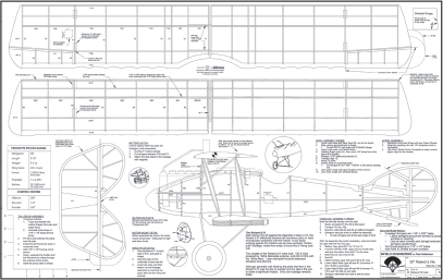
DOWNLOAD FREE PLANS!
TILED
FULL
Or purchase full plans here
Specifications
Construction: Balsa and plywood
Wingspan: 30 inches
Length: 21.8 inches
Flying weight: 9.5 ounces
Power: 1,700 Kv "Blue Wonder" motor; 12-amp ESC; 3.7-gram and 4.3-gram servos (two each); 7 × 6 APC propeller; 2S 1,000 mAh or 3S 500 mAh LiPo battery
Covering: Printed and plain tissue
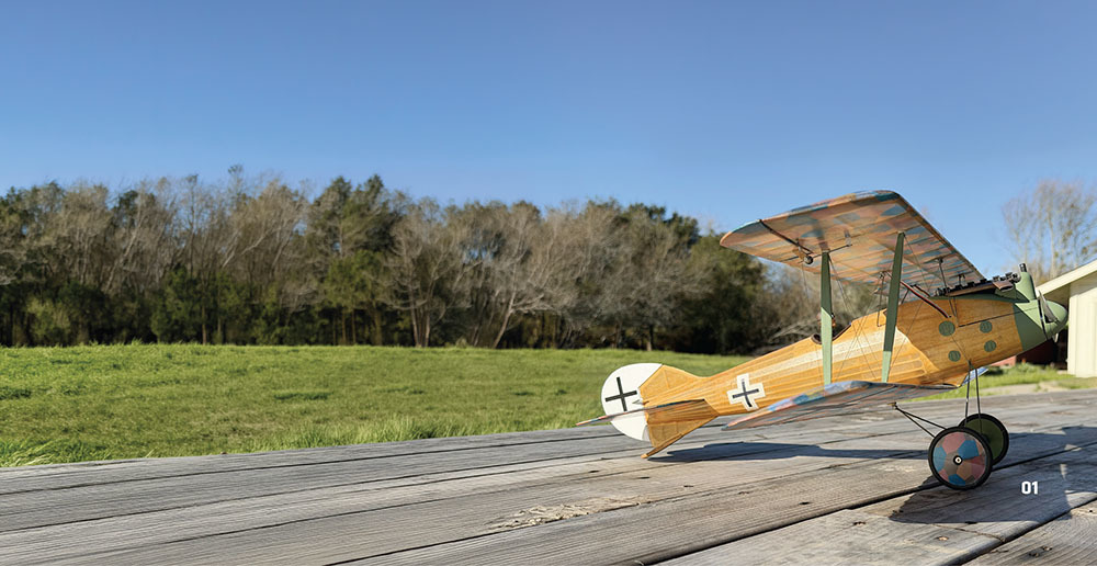
As Derek Micko explained in his article, this project is the result of our third "Fighter Face-Off." Derek and I have conspired periodically to design and build a pair of fighter aircraft that opposed one another in battle. This time around, we were challenged by the former executive editor of Model Aviationto take on a Dawn Patrol theme. In an effort to find two undermodeled aircraft, Derek selected the French Hanriot HD-1, while my subject is the LFG Roland D.VI.
The Roland D.VI was a respectable fighter that arrived late in World War I, but it was outclassed by the Fokker D.VII. Nevertheless, Roland received orders for its fighter as a hedge against any issues that might arise in Fokker production. There were 150 Mercedes-powered D.VIa aircraft completed. Another 200 Benz-powered D.VIb airplanes followed. The Rolands served well, but there were too few in number to make much impact on the war’s outcome.
The most distinctive feature of the Roland is its "Klinkerrumpf" fuselage. Unlike the more familiar plywood-sheeted Albatros, the D.VI fuselage was clad in long, wooden strips in the fashion of a Viking longship.
The base plan for this model shows the early D.VIa version. Later, the D.VIa received aerodynamically balanced ailerons. The D.VIb can be distinguished by its even larger aileron balancers and new balanced elevators. This plan includes outlines for the later variants.
Building the Tail Group
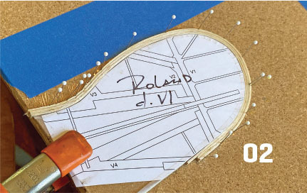
The outlines for the tail group parts are made from laminated balsa strips. Get started by tracing the outline from the plans onto thin wood or foam and cut out the forms. Soften 1/16 × 1/8-inch strips of balsa by soaking them in water overnight. Wrap the strips tightly around the forms one at a time. Carpenters glue between the strips works well on the wet wood. Set the forms aside until they have cured completely. They will hold their shapes after they are removed from the forms.
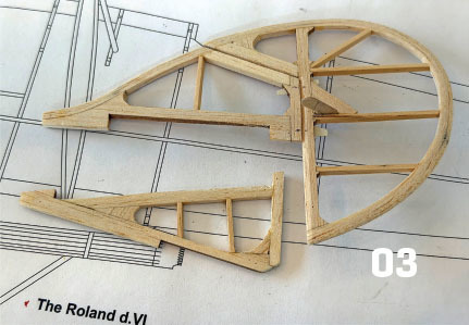
Pin the outlines over the plans and glue the kit parts in place in numerical order. Lastly, fill in the bracing by using 1/16 × 1/8-inch strip stock.
Once they’ve cured, remove the tail group parts from the board. Separate the fin from the rudder and the horizontal stabilizer from the elevators by cutting through the balsa outlines where it’s shown. Sand the parts with a round profile at the leading edges (LE) and taper the trailing edges (TE). Install hinges of your choice. For the prototype, I used thin strips of CA hinge material.
Framing the Fuselage
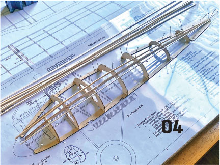
The fuselage is framed in the traditional "half-shell" method. Pin vertical keel parts K1 through K3 to the board. Glue the left-hand formers to the keels so that they stand perpendicular to the board. Tie these parts together with left-side keel K4. Note that K4 is longer than right-side keel K5—they are not interchangeable. This difference will ensure that cowling opening former F1 has the same downthrust and right-thrust angles as the face of the motor mount. Add a few stringers to hold the assembly together and allow it to cure.
Unpin the left side of the fuselage. Attach the battery tray to formers F2 through F4. Glue the right-side formers into place so that they are parallel with their left-hand mates. Tie them together with right-side keel K5 and a few stringers.
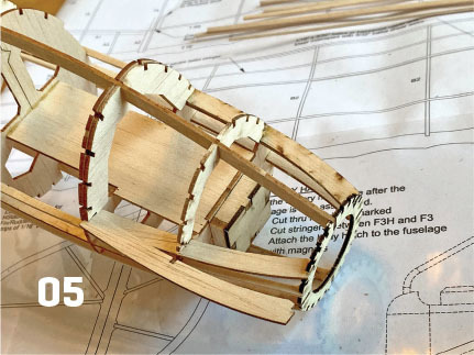
Build the battery hatch beginning with hatch formers F2H and F3H—glue these to K1 only. Slide lower hatch rails K6 and K7 into place, gluing their undersides to F1 through F3. Lastly, glue the upper sides of the upper hatch rails to F1, F2H, and F3H. Similar to the side keels, the hatch rails are right- and left-handed, so be sure to keep them in order.
Now that all of the kit parts for the fuselage are in place, add the 1/16 × 3/32-inch stringers. Dampening the stringers prior to their installation and alternating side to side and top to bottom will help avoid warps in the assembly.
Consider adding infill to the front of the fuselage. This entails filling the gaps between the stringers with soft balsa. The purpose is both to strengthen the assembly (behind former F1 and above and below the hatch rails) and to prevent the "starved horse" look (the droop in the covering where it spans a compound curve). Because the Roland has a lot of compound curvature in the nose, I opted to add infill to most of the area between formers F1 and F4. This is not a requirement.
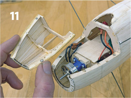
After completing the fuselage assembly, remove the battery hatch by cutting through keel K1, where shown, and through former F1 between the upper and lower hatch rails. Use magnets and aligning pins to hold the hatch in place.
Framing the Wing
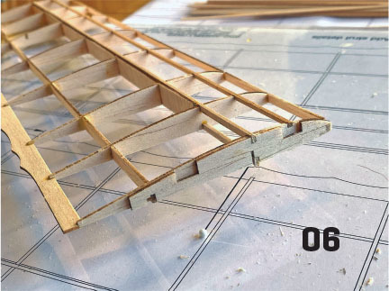
All four wing halves build very similarly. Begin by pinning rear main spar RS and the 1/16 × 3/32-inch lower main spar to the building board. Glue the ribs in next—all are perpendicular to the board except for bottom root rib B1. Use the dihedral gauge printed on the plans to set the angle of B1.
Now add the 1/16 × 3/32-inch upper main spar and the shear webs from the kit. Glue in the LE and a 1/8-inch balsa doubler in front of the LE. Add a 1/16-inch square stringer to the top of the wing behind the LE then glue in the TE. Lastly, glue in wingtip parts WT1 through WT3.
Only the upper wing has ailerons. Position aileron LE A1 against the back of RS, but don’t glue them together. This will be the parting line for the aileron. Glue in aileron riblets A2 through A4. To remove the aileron, cut through the TE, T5, and T6, where shown.
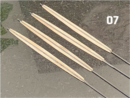
For the prototype, I used 1.5 mm carbon-fiber rod for the interplane struts. To flesh them out, 1/16-inch balsa strips were epoxied to the front and back of each carbon-fiber strut. This was then sanded to the shape shown on the plans.
Making the Wire Struts
A lot of builders state that bending wire struts is not fun. I won’t say that I look forward to it, but for this project, I tried something new that made it much less of a chore.
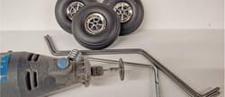
The patterns for each strut were transferred onto sheets of paper, which were then taped down to a piece of smooth plywood. A small nail was driven into the plywood at the inside corner of each bend in the pattern.
The bends were made by sweeping the wire around the nails. Because they were made while the wire was held flat against the plywood, all of the bends were kept in the same plane. This was a big improvement compared to my freehand technique. (For the record, it’s unlikely that I invented this technique, but it will be my go-to from now on.)
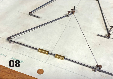
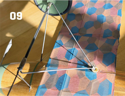
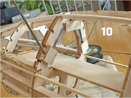
The undercarriage is constructed from three separate wire parts: the front strut, the rear strut, and the axle. To make assembly easier, I added two short pieces of brass tubing to the bottom of the front strut. During final assembly, the three undercarriage wires were held in position by plugging the axle and the rear strut into the tubes. These parts were silver-soldered together, although epoxy could also be used.
The cabane struts were bent into shape using the same technique. The front and rear struts were epoxied to their respective formers by sandwiching them with scrap balsa spacers and plywood caps.
Installing the Electronics
As always, there are as many ways to outfit a model as there are builders. I’ll share how the Roland prototype was outfitted, but other hardware and preferences might require alternate solutions.
Derek and I agreed from the beginning of this project that both of our aircraft would be powered by "Blue Wonder" motors. Marc at Rabid Models provided our motors and 12-amp ESCs, as well as the servos that are discussed later in this article.
The motor was placed on the front of the motor mount box and centered within the cowling opening. This was made easier by adding the propeller adapter and the spinner backing plate. The motor mount holes were marked on the firewall. They were not centered on the face of the motor mount—this was because of the right-thrust and downthrust angles that were designed into this model.
Holes were drilled into the motor mount face and tapped with the screws that were used to hold the motor. The screws were removed so that the holes could be hardened with CA, and then the motor was installed for good.
After trimming the side of the battery tray slightly, I was able to squeeze the ESC just behind the firewall on one side and the receiver under the other side. This helped get some weight forward.
Two 4.3-gram servos were mounted to scrap balsa rails to operate the tail group. I like to use pull-pull for the rudder, which is appropriate for the Roland because all of its control surfaces were cable operated. I opted, however, for a sleeved rod to control the elevators.
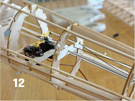
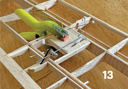
A pair of 3.7-gram servos were used to operate the ailerons. A box made from balsa scrap was framed into a rib bay. The lid to the box was siliconed at the corners so that it could be removed if a servo failed, and then a servo was siliconed to the lid. A short control rod was fashioned with a Z-bend at one end and a Du-Bro EZ Connector on the other.
Putting It All Together
Following Derek’s lead, the Roland was covered with tissue. I purchased tissue printed with 1/12-scale five-color lozenge from Hummingbird Model Products for the wings and horizontal tail. Plain tissue was found in the giftbag stash.
The tissue was attached with Mod Podge that was painted full strength onto the wooden frame. After the Mod Podge dried, the tissue was spritzed with water and gently stretched over the frame. A trim iron was used to activate the Mod Podge.
The covered model was doped with Minwax water-based polyurethane that had been thinned 25% with water. A bit of food coloring was added to dope the fuselage, which resulted in a color that resembled the woodwork of the only surviving Roland D.VI in Kraków, Poland.
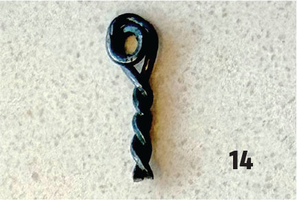
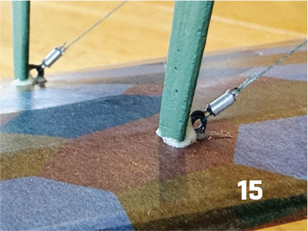
After assembly, the Roland felt sturdy enough, but the flying wires were calling my name. I made tiny eyelets by twisting soft steel wire around a 1/16-inch drill bit. These were inserted into holes that were drilled into balsa mounting blocks in the wings and fuselage. The eyelets were rigged with 10-pound test Kevlar fishing line. Tuning was made simple by wrapping each line through its eyelet twice then running the tag end through a "turnbuckle" that was made from a short bit of 1/16-inch aluminum tube. Once I was happy with the tension in the line, the tube was filled with a drop of thin CA to lock the line in place.
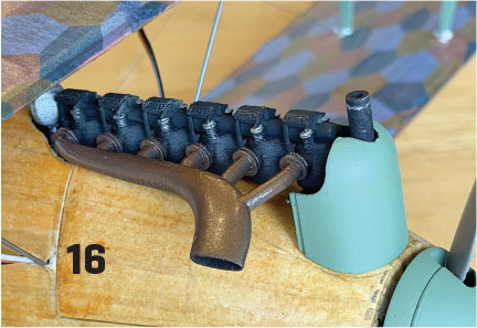
The last topic to discuss is the 3D-printed detail parts. Like the Fokker D.VII and many Albatros aircraft, the Roland needs a big inline motor rising out of the cowling. I’ve prepared an STL file of the appropriate Mercedes motor and its giant exhaust manifold for the D.VIa. The file also includes the curved front cowling. This file and another for the Roland’s bowl-shaped spinner are available as free downloads on Thingiverse; the link is listed in "Sources."
Flying the Roland D.VI
After weighing in at 9.5 ounces with a 3S 500 mAh LiPo battery installed, the little D.VI was ready for a maiden. I was surprised by the ground handling—steering with a fixed skid worked pretty well with just a little speed. As a result, the takeoff run was very straight, and it lifted off after a 15-foot roll.
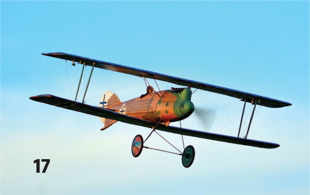
Power on 3S was more than adequate. I did more trimming to cancel out a dive than I would have liked. This has been corrected in the final plans by adjusting the wing’s angle of attack. Once it was trimmed, the Roland felt very sturdy and predictable in the air.
Similar to most WW I subjects, the Roland has a lot of drag. It slows down really fast when the power is chopped. It also appreciates the use of rudder to make smooth turns. Rolls are a bit slow, but it will readily do all of the basic maneuvers.
A final approach made with 10% throttle results in an amazingly straight descent. Again, typical of WW I models, the Roland tends to nose over even after a promising approach.
Wrapping It Up
The only thing left with this third Fighter Face-Off is for Derek and me to get together for a Dawn Patrol meetup. Until then, build light and fly low!
SOURCES:
"Infield Engineering Roland d.VI Fighter Face-Off 3"
RCGroups
rcgroups.com/forums/showthread.php?4800609-Infield-Engineering-Roland-d-VI-Fighter-Face-Off-3
Rabid Models




Comments
Add new comment