
Free Flight Duration
By Louis Joyner | [email protected]
As seen in the February 2025 issue of Model Aviation.
FREE FLIGHT (FF) models come in all sizes. Small ones are easy to store and transport, but larger models with wingspans of 5 or 6 feet or more and long fuselages can be a challenge to store or transport.
One solution is to design and build larger models so that the long sections (e.g. the fuselage and wing) can be easily taken apart for storage or transportation. Wing halves can be joined with a steel wire. Fuselages can be built in two sections. For rubber models, the logical place for the break is behind the rear motor peg. (Because of higher flight stress, gas-powered models typically have one-piece fuselages, as do Towline Gliders.)

Throughout the years, I’ve built dozens of models with two-piece wings and fuselages. I’ve also collected three or four model boxes. Most are approximately 3 feet long and 1 foot wide. Thickness varies from 4 to 6 inches. Two of the boxes are converted molded-plastic rifle cases. Another is a purpose-made aluminum FF model box. I’ve also made several boxes from thick cardboard to provide extra storage in my shop.
Blue Max MK-11
I am currently building Masabumi Shibachi’s Blue Max MK-11 F1B Wakefield. Detailed plans were published in the 1979 National Free Flight Society (NFFS) International Planbook. Because the model was designed and the plans published before 1980, it is legal for the Nostalgia Wakefield event.
The Blue Max is not a typical Wakefield. It looks more like an overgrown Hand-Launch Glider. The two-piece, four-panel wing spans 1,500mm—approximately 5 feet. Construction uses a solid balsa front section instead of a built-up D-box. The front portion of the fuselage is a rolled balsa motor tube covered with fiberglass cloth and epoxy. The two-piece wing is mounted directly on the top of the fuselage at +4°. A fiberglass rod connects the rear of the motor tube to the rudder and stabilizer.


The two-blade 620mm-diameter propeller is set at 5° right-thrust and zero downthrust. The center of gravity is set well forward at 33% of the wing chord.
A tapered cone provides an elegant transition from the 36mm-diameter motor tube to the 8mm fiberglass rod. There was no indication that the cone was fixed or removable. I decided to make the cone and tailboom removable to allow the model to fit in a smaller box. The total fuselage length is 1,210mm—approximately 4 feet. With a two-piece wing and fuselage, the model could fit easily into a 3-foot model box.
I whittled a cone from a block of balsa and drilled a center hole for the tapered carbon-fiber tailboom, which was then epoxied in place. A cylindrical balsa plug was sanded to fit in the rear of the motor tube.
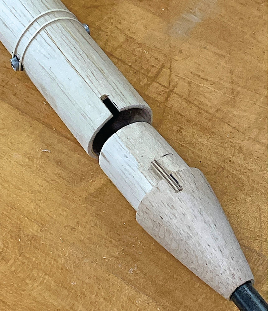
The motor tube was then blocked up on a flat surface and the plug partially inserted into the rear of the motor tube, leaving 1/16 inch sticking out the rear. Next, the tailboom was carefully aligned with the motor tube, and the motor tube plug was glued to the face of the cone.
After the glue dried, a rod was inserted into the front of the motor tube to push out the attached cone. The tailboom and motor tube were then fitted together and the cone was sanded to give a smooth fit with the motor tube. To ensure alignment, matching notches were made in the top rear of the motor tube and the cone of the tailboom. A small piece of 1/8-inch plywood was attached to the cone to provide an alignment key. The two fuselage sections fit tightly together without the need for a locking pin or rubber bands.
The only problem so far is where to locate the tracker and remote dethermalizer (DT). I might have to use a fuse DT at the rear of the tailboom, as was done on the original model.
Covering awaits.


Comments
Add new comment