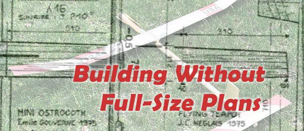
By Louis Joyner | [email protected] As seen in the October 2022 issue of Model Aviation. WHY WOULD ANYONE DO THAT? There are hundreds of full-size Free Flight (FF) plans that are available from a variety of sources, but what if you want to build a design from the past and can’t find full-size plans? That was my problem when the Vintage Wakefield event was announced a few years ago. After a lot of searching through National Free Flight Society (NFFS) publications from the 1960s and 1970s, through the last Frank Zaic Model Aeronautic Yearbook, and Bill Hartel’s World Free Flight Review, I had narrowed my choices to roughly a half-dozen designs. All of these had nicely drawn three-views, but no full-size plans were available. One of my choices was Jean Claude Neglais’ Flying Teapot. The threeview drawing was in the 1979 NFFS international Symposium report. Jean Claude had written a Sympo paper on the experiences of three aeromodelers from Eastern France: a bricklayer (Emile Gouverne), a draftsman (J.C. Neglais), and a priest (Jean Wantzenriether).

The replica Teapot proved to be an easy build, despite some unusual construction features. The group was experimenting with high-aspect-ratio wings for Wakefield Rubber models. A 16:1 wing was considered their "wind and storm" model. For early morning or calm weather, aspect ratios were in the 20 to 26:1 range. Emile even built a model with a 47:1 wing. The text for the paper was in both French and English, and the threeview plans notes were in French, with the measurements in millimeters. (I have been designing and building using the metric system for many years and find it much easier to use than inches.) The only problem with the Flying Teapot three-view was that not everything was dimensioned. For example, the nose-to-wing leading edge (LE) length and the wing trailing edge (TE) to stabilizer LE were called out, but the length of the motor tube and the length of the tailboom were not shown.

The stabilizer was built upside down in a hotwired foam form. This allowed easy access to glue the ribs in place. Luckily, the wing plans showed the spacing between each rib. I ended up using the wing drawing as a ruler. For example, I made tick marks on a piece of paper that indicated the stabilizer chord and the stabilizer semispan and used the rib spacing dimensions on the plans to determine the size of the stabilizer (85mm × 410mm). This technique was also used to determine the motor tube diameter and length, tailboom length, and the wing chords at root and tip. The three-view included cross-section drawings of the wing root and tip ribs, as well as the stabilizer airfoil. These were probably drawn full size on the original three-view, but the drawing was reduced slightly to fit the NFFS publication’s format. I used my copier to enlarge the wing and stabilizer cross sections to the correct size. These were then used to make rib templates. There was no need for full-size drawings to build the model. The wing was sheeted on top and bottom with wide balsa LEs and TEs. All I needed to do was cut the bottom sheets to size and draw the rib locations directly on the balsa. As with every undercambered wing I’ve built in the last half-century, the wing was built on a cambered jig. The motor tube and tailboom were rolled balsa, so no plans were necessary. The rudder was drawn to size directly on a lightweight sheet of 1/32-inch balsa, ribs were added, and a second, slightly wider sheet was added. The left side of the rudder is flat, so it lifts to the right for a left turn in the glide. To make trimming easier, I pivoted the rudder so that it could be easily adjusted. A short piece of thin wire extends from the bottom rear of the rudder. A strip of tape holds the rudder in position, but this can be easily adjusted. When the best rudder offset was determined, the tape was removed and the wire was glued in place.

The Flying Teapot shares a page with the Mini-Ostrogoth. Both French Wakefields were designed in the 1970s and can be flown in Vintage Wakefield. Rib-spacing dimensions served as a ruler to help in building a modern replica. Building the stabilizer was challenging. The airfoil is semisymmetrical and the top is sheeted. The only way I could make the stabilizer was to build it upside down. I made two plywood templates that matched the upper camber and hot-wired a foam form. The 1/32 sheet was cut to shape and the LEs and TEs were added. The rib locations were drawn on the lower surface of the sheet. I lightly wetted the upper surface and placed it upside down on the form. Weights were added to hold the balsa down on the form. After a day or two of drying, the ribs were added. Next, the bottom was covered with tissue. After doping, there was a slight bow downward at the tips. On a later stabilizer using this same construction, a lower spar was added to reduce bowing. The tiny pylon was no doubt where the model got its name. Unlike the original model, which used a fuse dethermalizer (DT) sticking out of the side of the pylon, my more modern replica needed to fit a tracking transmitter and a remote DT receiver, battery, and servo into a tight space. Somehow it all fit. To help support the two-piece wing, I added plywood that extends out from each side of the pylon and matches the dihedral angle of the wing center section. This was made by sawing the correct angle in a piece of 3/4-inch thick pine, and then laminating four strips of 1/64 plywood on the form. The finished piece was then notched into the pylon at the location of the wing spar. Four 1/8-inch dowels radiate out from the pylon to anchor the rubber bands that hold the wing in place. The Flying Teapot uses the Piqueur Gravité Incidence (PGI) trim developed by Jean Wantzenriether. As shown on the plans, 3° of downthrust are used to vector the thrustline through the aircraft’s center of mass. This is slightly above the model’s center of gravity, which is at 63% of the wing root chord. The wing is set at -1° and the stabilizer is set at -3°. My first chance to fly the model was at the 2021 Outdoor FF Nats. Test-flying time was limited, so I only got in two lowpower flights the morning of the Vintage Wakefield event. The model’s third flight was its first round in the contest. The climb was good, but the glide gradually began a slow, shallow spiral to the ground. There was no damage, but I did lose some time. A bit of left turn was taken out of the rudder and the next three flight were maxes. The last flight dropped a few seconds, putting me second behind Chris Matsuno, who maxed all five rounds, flying his own design that was built in the 1970s.


Comments
Add new comment