
Written by Jim Ryan Build and fly the 1960s US Army attack helicopter Construction As seen in the December 2011 issue of Model Aviation.
Order Plans from AMA Plans Service
Image
Image
Specifications:
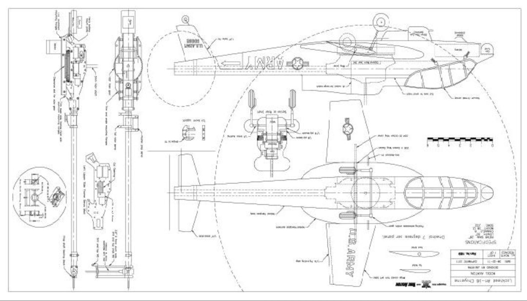
Rotor span: 28 inches (711mm) Length: 30 inches (762mm) Weight: 38 ounces (1077g)Gear Used:
Transmitter: Multiplex Royal Evo 12 with Spektrum conversion Receiver: Spektrum AR9000 Servos: Cyclic Hitec HS-5055MG Tail: JR DS287MG Motor: Scorpion HK-2221-12 ESC: Castle Creations Phoenix 35 Battery: 2200-3S LiPo Accessories: Align GP750 heading-hold gyro and Castle CC-BEC unitImage
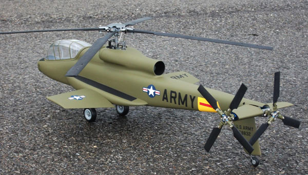
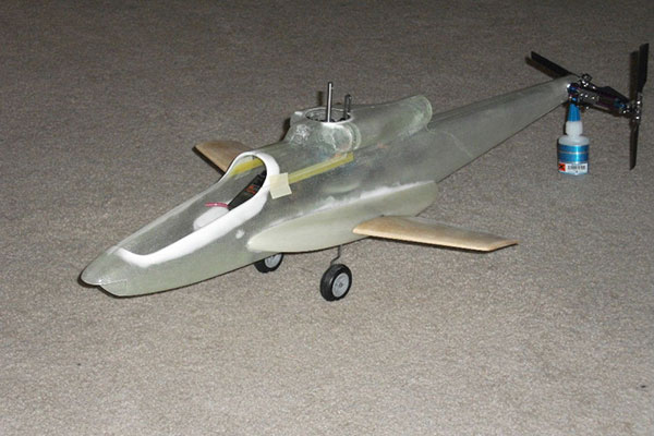
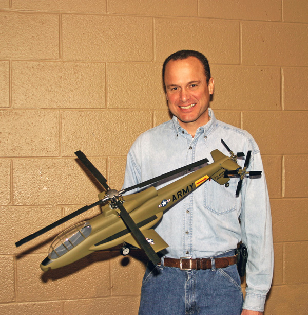
This static shot shows the scale four-bladed tail rotor and three-bladed pusher propeller. Callie Graphics supplied the CNC stencils.
Introduction
In the late 1960s, the US Army contracted with Lockheed for the construction of a revolutionary attack helicopter called the AH-56 Cheyenne. In addition to the normal tail rotor, the Cheyenne had a variable-pitch pusher propeller. For hovering and low-speed flight, the propeller would spin at flat pitch, but for high-speed flight the propeller would gradually increase pitch, propelling the Cheyenne to higher speeds until its stubby wings were providing most of the lift. At this point the main rotor was running nearly flat pitch, but it continued to provide pitch and roll control. This ingenious design gave the Cheyenne unprecedented speed and range. In addition to its unique propulsion system, the AH-56 incorporated a number of other novel features that would eventually become standard on the next generation of high-performance attack helis. These included a rigid rotor head, terrain mapping navigation, and helmet-mounted sights. Progress on the project was slowed by the ongoing war in Southeast Asia, and by the early 1970s the Army was becoming increasingly focused on Soviet armor. In the end, the Pentagon changed its mind and decided that instead of a high-speed gunship, it really needed a tank killer that would use terrain as its main defense. The AH-64 Apache was the result, and it has served capably for more than 30 years. As a lifelong aviation nut, I was fascinated with the Cheyenne program when I was a kid. I was disappointed when it was canceled, so nearly 40 years later I decided to design my own AH-56, based on mechanics from the ubiquitous Align T-Rex 450. The key to making this project feasible was Align’s release of a torque-tube tail retrofit kit, because this was the only practical way to drive the complex tail gearbox. With this important requirement checked off, I set out to build my own Cheyenne.Builder Notes and Considerations
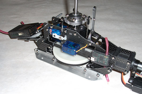
Replicating the compound tail of the original Cheyenne was central to the project. The tail unit adds a degree of complexity, and some builders may opt to go with a normal tail rotor. I wanted the body to be as true to scale as possible. Because the Cheyenne was an unusually long and slender helicopter, this imposed some challenges to fitting the mechanics inside. A standard 150-tooth main gear is too large to fit inside the fuselage. The builder can cut clearance slots in the fuselage sides, but I opted to modify the mechanics to use a smaller 132T gear.Image
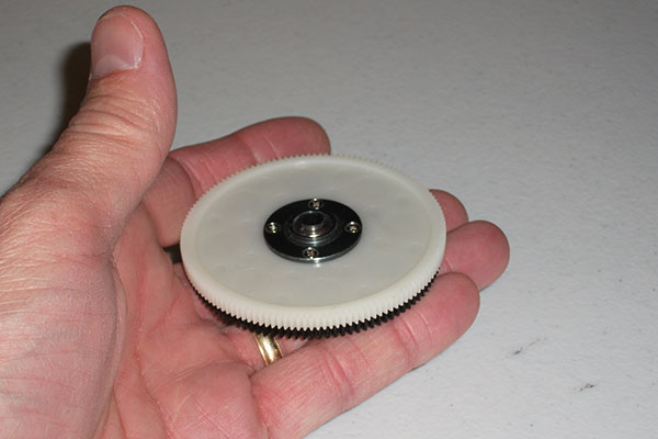
To fit inside the body, the stock main gear needs to be replaced with a 132-tooth gear. The author machined out the hub on the gear so it could be mounted in a standard Align gear hub.
The low fuselage profile doesn’t provide enough height for a standard 450-size motor. I opted to cut a clearance hole, which also provided cool air to the motor. During the construction steps, I’ll outline my solutions to the various challenges that arose, but I’ll also offer alternatives that will simplify the build. This advanced construction project requires machining and fabrication skills beyond those usually required for a helicopter build.
Tail Unit
The tail unit on the prototype was fabricated using parts from the Align torquetube conversion kit. Because an extra gearbox side plate was needed, I purchased a spare tail unit as well. The standoffs for the extended tail-rotor mount were fabricated from 4mm aluminum knitting needles, cut to 2½-inches (63.5mm) in length, with the tips drilled and tapped for M2 screws. The extended tail-rotor shaft is a 120mm piece of 3mm stainless drill rod, and the modified bevel gear was secured on the shaft with J-B Weld.Image
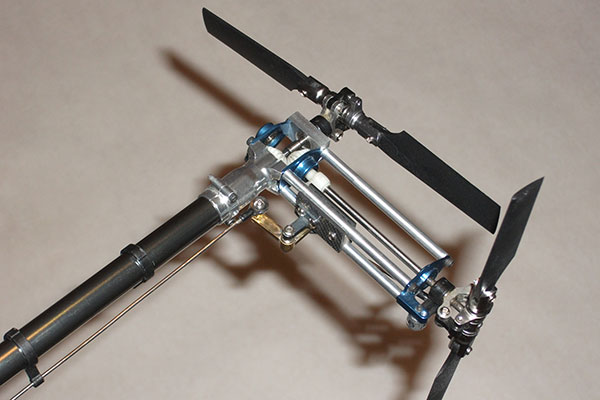
The compound tail unit, featuring 2½-inch long aluminum stand-offs, the offset bellcrank, and the tail-rotor pitch linkage, is the most complex part of the build. The thrust collar on the tail-rotor shaft keeps the bevel gears from driving together.
Pitch control on the tail rotor was achieved by fabricating an offset bellcrank, with a pivot arm to keep the pitch-control slider from flopping around. The pusher propeller can be controlled with a simple straight pushrod. The one component in the tail unit that requires real precision is the rear bearing block. Although not complex in shape, the holes for the mounting screws and the center hole for the propeller-shaft ball bearing must be perfectly centered if the propeller is to spin without runout. The pusher propeller shaft is a spare tailrotor shaft, press-fit into the bevel gear. Again, drilling this hole precisely on center is critical, so using a lathe is a necessity. With the tail unit completed, I installed it on an otherwise stock T-Rex 450 (with the main rotor assembled for counterclockwise rotation) and logged a series of test flights. These tests revealed no major handling problems, and the pusher propeller proved to be effective.
Main Frame
The main frame is primarily the upper side plates for a stock T-Rex 450- V2. The mounting flanges were cut from ½- inch aluminum angle stock from the hardware store. Because of the thickness of the aluminum, I increased the length of the lower assembly screws to 16mm. I trimmed the lower side frames flush with the bottom of the mounting flanges.Image
The main frame was built using modified T-Rex 450 parts. The rear (pitch) cyclic servo needed to be relocated to avoid touching the body. The aluminum mounting flanges were cut from ½-inch aluminum angle and installed with 16mm socket-head screws.
To get the rear cyclic servo to fit inside of the body I had to relocate it as shown on the plans. This is a relatively simple modification that I’ve used on previous scale helicopters. As noted earlier, in order to have the mechanics completely concealed, I opted to replace the stock 150T main gear with a 132T gear. This led to two or three other changes. I had to modify the motor mount to allow the motor to slide far enough to mesh with the teeth of the smaller gear.
Image
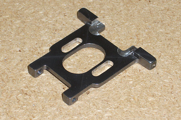
If you opt for the 132T main gear, you’ll need to mill the slots on the motor mount. This allows the motor longer travel to engage the smaller main gear.
I also had to grind down the base of the pinion so that it wouldn’t rub on the autorotation gear. You can save some trouble by using the stock gear train if you don’t mind cutting clearance slots in the body.
Body
With the mechanics thoroughly tested, the next step is installing them in the body. The Cheyenne’s fuselage is slender by scale helicopter standards, and careful planning is needed to get everything to fit.Image
With the smaller hatch option, the mechanics are a tight fit. The hatch opening was reinforced with .030-inch G-10 fiberglass, but 1/32 plywood would work just fine. The larger hatch option makes installation easier.
For my build, I elected to use a removable canopy for battery access, and I made the hatch between the cockpit and main shaft as small as possible. This works, but easing the mechanics through the opening is a very tight squeeze. You could make your life easier if you cut the hatch to the larger opening shown on the plans. This works particularly well if you opt to cut clearance slots for the stock 150T main gear. After cutting the hatch opening, the 1/8-inch plywood bearers are epoxied into place. These have 4-40 blind nuts fitted for securing the mechanics and 1/16-inch vertical doublers to provide reinforcement for the wing joiners and landing gear.
Image
The removable canopy has a balsa cockpit floor, finished with resin-saturated paper. The hatch has a plywood tab at the rear and is secured with ¼- inch rare-earth magnets at the front.
After drilling holes for these and test-fitting the landing gear, I glued the molded sponsons in place with thin CA. Note that the sponsons stiffen the forward fuselage significantly.
Stub Wings
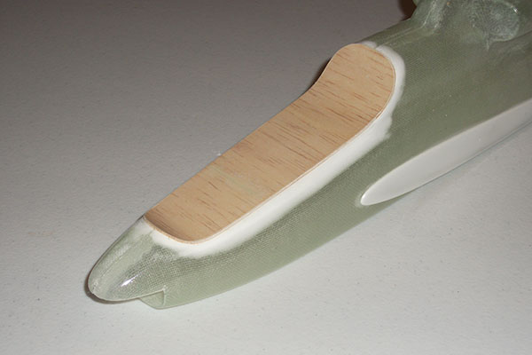
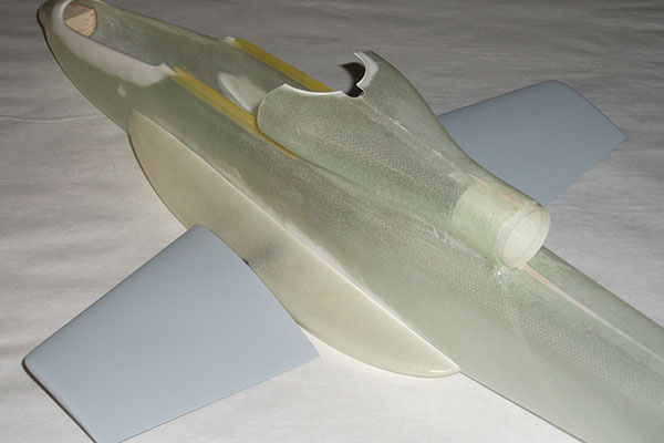
I elected to carve the small wings from soft balsa, and I mounted them to the body using carbon-fiber joiner tubes from The Composites Store Inc. (CST). I molded their roots using Bondo, reinforced the TEs with a ¼-inch strip of 1/64-inch plywood and finished them with ½-ounce fiberglass cloth.Image
The wings are carved from soft balsa, and the sharp TEs are reinforced with ¼-inch strips of 1/64 plywood. The joiners are snug-fitting carbon-fiber tubes, and music wire pins through the joiners lock the wings in place.
Landing Gear
The retractable landing gear folds backward into the sponsons. There are several ways to actuate the gear, but I opted for a simple gear train built with RC car pinions. I used a metal gear microservo to actuate the gear.Image
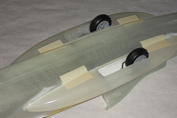
The retracts fold back into the sponsons. The prototype’s actuation system was gear-driven, but a bellcrank will also work. Install carbon fiber or 1/16-plywood doublers at the front of the retract openings to provide a positive stop.
Finishing
The preproduction Cheyenne wore a number of color schemes during the life of the test program. I opted for the standard Army markings shown on the example at the Army Aviation Museum at Fort Rucker, Alabama. I generated CAD drawings for all of the markings and ordered paint stencils online from Callie Graphics. Callie has terrific service, and the price was surprisingly inexpensive. The overall color scheme was done with Testors Model Master enamel paints, and applied with an airbrush. The body was then clear-coated with matte lacquer.Test Flying
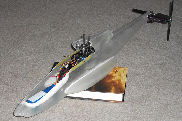
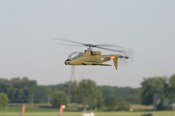
My first priority was to get the mechanics flying, and I logged more than 50 flights in that configuration before I added the body. With the propeller at flat pitch, the Cheyenne flies similarly to a stock T-Rex except that it’s slower because of the propeller disk drag. As propeller pitch is increased, the helicopter accelerates forward, and top speed is impressive. There’s very little pitch change and no adverse handling issues with the pusher propeller, and the heli carries more speed into vertical maneuvers with the added thrust. I logged all of my early flights with a standard flybar head, reversed for counterclockwise rotation. For a better scale appearance (and greater lift) I switched to a Black Angel four-bladed head, with weighted scale blades. You could certainly stick with the stock flybar head and save some weight in the process.Image
The exhaust pipe is a rolled strip of paper, saturated with finishing resin. Once cured, it’s trimmed flush with the opening.
After your initial test flights, I recommend adding ballast to the mechanics to approximate the weight of the completed helicopter. This gives you a chance to preview the handling characteristics and to make any needed tweaks to the head speed and pitch curve. The completed Cheyenne made its flying debut at the 2011 IRCHA Jamboree. After working out some issues with controller programming, the heli flew beautifully, meeting all my hopes for the project. With the added lift capacity of the four-bladed head, the Cheyenne doesn’t handle at all like a heavy Scale model. In subsequent flights the Cheyenne continued to improve. At flat pitch, forward flight is slow and predictable, and the pusher propeller can actually be a benefit because there’s little chance of the heli getting away from you. At full propeller pitch, the Cheyenne accelerates briskly and really comes to life. It’s truly a delight to fly.
Image
Conclusion
Designing and building the Cheyenne was one of the most challenging projects of my RC career, but also one of the most rewarding. Building the complex tail went smoothly, and the real challenges didn’t begin until I had to squeeze the mechanics into the slender fuselage. The good news is that all these puzzles have been solved, so your build should go easily.Image
The Cheyenne placed first in the Helicopter Class at the 2011 Toledo Weak Signals Expo. Note the attack heli’s compact size.
Sources:
CST: The Composites Store (661) 822-4162 www.cstsales.com/index.html Callie Graphics[email protected] www.callie-graphics.com Testors Model Master paint www.testors.com IRCHA www.ircha.org


Comments
AH 56
Very very nice I see you got your model to fly the Army could not keep them from running into the ground
AH 56
Jim is a engineering mastermind, getting the tail rotors true to scale.
I'm always wondering what's next with him. ..
AH-56 Cheyenne
While looking for plans for a scale helicopter model, I just stumbled over this project. Great work!
As I am a scale RC helicopter enthusiastic, I have just ordered the plans to make my own.
Thanks.
This is the first time I've
This is the first time I've seen this site. I've only looked for sites on the actual AH-56. I beg to differ with Mr. Beatty's comment. I was in the US Army, 3RD Aviation Company which was formed to test the Cheyenne. The Army never received the helicopter to test. Lockheed lost two or three while testing, one at sea. The 3rd Aviation Company became a Cobra company after Lockheed's contract was not increased for more than the original 10. I have searched for years to get into contact with the men of the 3rd Aviation Company only finding two.
Thought I would add to your
Thought I would add to your comment
Don lodge was a test pilot for the Cheyenne
He and my dad John minasian were friends I beleave it was in the late 70s and got together and scratch built the Cheyenne out of fiberglass it had 6 blades for the main rotor three blade pusher and two blade tale rotor
Shluter was given a fuselage that he copied without permission and put it out on the market .
The Cheyenne is in the Los Angeles science and industry museum.
it flew many times had even thrown a main rotor blade and was landed without damage
John also worked at Hughes Helicopters on the apache
Mr Beatty nice job on yours
AH 56 Cheyenne
Are the plans still available? I olled for the order form but could not locate it.
Our apologies, we see the bug
Add new comment