
Written by Lee Estingoy
Technical
As seen in the November 2010 issue of Model Aviation.
Mysterious events are often attributed to mystical causes, and brushless power systems are about as mysterious as things get in RC. Some systems work and others don’t. Why?
The usual explanation is something along the lines of, “It’s a mystery!” The reason for a component failure is a mystery to most involved, but understanding a bit more about brushless systems can go a long way toward helping a hobbyist enjoy outstanding reliability in an electric-powered airplane or helicopter.
A brief description of the role of the brushless Electronic Speed Control (ESC) is that it must accurately make and break connections between the three input leads of the motor and the power source to drive the rotor magnets around the arc of the power plant. The most accessible way to describe the operation of the ESC is to break it down by functional sections.
A brushless ESC uses a microprocessor to manage the operation of field-effect transistors (FETs), using information from a rotor position circuit. Let’s look at each of these more closely.
Making the Connection
Before we go too far, let’s make a few things clear about the operation of a brushless motor. It uses three sets of copper windings to push and pull permanent magnets attached to the shaft inside the power plant. It’s important to understand that these windings are connected at one end inside the motor. There are two ways this connection is made; one is the Delta, or D-wind, and the other is the Y-wind. The controller doesn’t care which is used; the windings need only to be connected. The type of connection does affect the torque curve of the motor.
The two wind termination types are known as a Delta and a Y-wind. Delta wind gets its name from the Greek symbol. It’s not much of a jump from there to understand the name for the Y-wind. A Delta-wind motor generally has nearly twice the Kv of a similar motor with a Y-wind.
Let’s call the three motor wires “A,” “B,” and “C,” and their “free” ends, those that stick out of the motor, are connected to the ESC. The ESC uses electronics to connect any of these wires to positive or negative, to achieve one of six possible combinations that results in an electromagnetic field in a precise location in the motor. The timing and duration of these connections is critical—and unbelievably short. Mechanical switches are simply incapable of the task. But high-power electronic switches—known as Metal Oxide Semiconductor Field Effect Transistors (MOSFETs, or FETs for short)—can turn on and off in a fraction of a second and are ideally suited for this application. Let’s do a bit of math to get an idea of the incredible activity going on inside the ESC. An outrunner motor with 12 poles that has a Kv (rpm per volt) of 1,500 and is powered with 24 volts (6S Li-Poly) will spin at 36,000 rpm (24 x 1,500 = 36,000). The six coil combinations needed for a full magnetic rotation must be repeated for every north pole in the motor. The example motor has 12 poles, so the controller must switch the FETs 36 times per revolution of the shaft (6 north poles x 6 steps per magnetic rotation). That means there are 1,296,000 electrical cycles per minute (36,000 rpm x 6 winding phases x 6 poles = 1,296,000), or 21,600 cycles per second. The controller must successfully switch between the phases every 1/21,600 second!

This is a basic drawing of connections required to drive a brushless motor. The three motor wires—A, B, and C—can each be connected to positive or negative poles of the power source by the ESC. The six possible combinations are numbered, and color-coded letters indicate connections and polarity at each point in the process. Red indicates connection to positive; black indicates connection to negative.
FET Drive Circuitry
Turning an FET on and off is not as easy as it might sound. Each has three connections: gate, source, and ground. To turn the FET on and create a circuit, the gate leg has to be driven to a point that is 5-10 volts higher than the voltage of the source leg on the FET, whichis connected to the motor power source. Refer to the simplified ESC diagram. If using a 4S Li-Poly battery, +IN will be roughly 14.8 volts (3.7 volts x 4). The gate requires 24.8 volts (14.8 + 10 = 24.8) for proper operation. The ESC must therefore be able to boost some of the power it takes from the batteries to the increased voltage to drive the FETs.
There are four main functional groups in an ESC: the power MOSFETs, the MOSFET driver circuitry, the microprocessor, and the motor position detection circuitry. A Battery Eliminator Circuit (BEC) is present in some controllers; it reduces the voltage of motor batteries to a level that is useful to the radio system in the vehicle.
Motor Position Detection Circuitry
The ESC has to know the precise location of the rotor magnet(s) to accurately sequence the connections that the FETs make. This is the trickiest thing that the ESC has to do. There are two main ways to go about this: sensored and sensorless. Sensored systems use electronic (Hall) sensors in the motor to track the rotor. This requires additional parts in the motor (sensors) and an additional wiring harness to connect the motor sensors to the controller. Sensored motors and controllers are popular in RC car applications, because they provide a slightly smoother motor start than the sensorless controller. Sensored systems were popular in the early days of RC brushless aircraft power systems; however, they are generally considered to be less reliable and less efficient than sensorless systems, so they are no longer popular for such applications. Sensorless/modern ESCs detect the rotor position through the power wires by “listening” to the third wire for signs of motor position while the power to the motor is applied to the other two leads. The changing magnetic field caused by spinning magnets in the power plant generates a voltage in the third wire, and sensorless ESCs detect and measure that voltage to determine how far the rotor has turned. Then the information is used to switch FETs as needed to cause correct magnetic push or pull in the phases.
Current can flow in either direction on each of the three motor wires, making six possible combinations of current flow. This diagram shows one. The blue path traces current flow from the battery through the FET, controlling the “high” side of the red motor wire (A), to the motor windings and back through the black motor wire (C) and the FET controlling that phase’s low side. ESCs vary throttle by switching the low-side FET on and off rapidly during the period that a phase is powered; this is the PWM rate. The purple path traces the “backflow” in the third motor wire (B) of current generated by the motion of the rotor magnets relative to the windings. The rotor position circuitry measures voltage of this current to determine when to switch the FETs to drive the rotor around inside the motor.
The Microcontroller and Its Firmware
The microcontroller is the “brain” that runs the whole operation. Operating a brushless motor takes tremendous computing horsepower, and better controllers use processors that operate at 25 MIPS: 25 million instructions per second. Controllers with less-capable processors might be unable to process the data quickly enough to run high-pole-count motors at high speed, because they hit a computational redline long before the motor reaches its full rpm/power capability. This is particularly true with high-pole-count outrunners in high-rpm (geared) applications, such as helicopters. Microcontrollers run software in much the same way that computers run programs. The software must manage a number of processes taking place simultaneously in the motor/controller system.
Typical ESC power board designed for the Power Pack FETs. Two phases are color-coded; blue pads = motor wire connection, green and red pads = FET drains and sources, and orange pads = gate connection.
I’ve mentioned how the controller switches FETs and keeps track of the motor position. Don’t forget that the microcontroller also has to process input from the receiver to compute the desired output power and flash indicator LEDs. The user might not want to run at full throttle all the time, so we have to be able to limit the output power by pulsing those FETs between the usual positional pulses. If that’s not enough, there may be special routines that govern motor speed, record data, monitor battery voltage, watch for overcurrent or overtemperature conditions, and manage activities of the switching BEC.

Typical ESC power board designed for the older S08 FETs. Two phases are color-coded; blue pads = motor wire connection, green and red pads = FET drains and sources, and orange pads = gate connection.
There is a lot going on here!
Input Capacitors
The large tubular devices that are an obvious part of most ESCs are capacitors. These are essentially fast-acting reservoirs for electrical power, and ESC designers use them to smooth out the power as it enters the controller. But why is this an issue at all?
Improvements in FET packaging, the way the internal silicon components are connected to the circuit board, play a huge role in the improvement of the ESC in the past few years. The older S08 packaging (L) connects with the tiny legs, while the huge Drain pad on the newer Power Pack FET (R) provides a much larger connection to the circuit board. The net effect is that much more of the heat generated in the Power Pack FET can be transferred directly to the circuit board.
Remember that the FET gates need to see a stable voltage to operate properly. In practice, the voltage that comes from the battery is not a constant value; a graph of battery voltage would look like spurts of voltage. Each spurt starts at a higher level than at which it ends during each power cycle of the FETs, however incredibly brief. A graph of this would look like a ripple. This changing voltage is called “Ripple Voltage.” ESC designers can smooth out this ripple to some extent by using capacitors, but there is a limit to how much the capacitors can fix. The FET gate must be 10 volts higher than source. If the source is crashing and recovering a bit between each cycle, the voltage in the gate circuitry might unexpectedly meet/exceed the 10 margin over the source voltage in the FET. That causes the FETs to turn on unexpectedly— and create nasty connections in the controller that typically lead to a bad day at the field. It’s not such a bad thing if the FETs turn off. It is bad when they all turn on at the same time that the smoke comes out. Advanced topics in ESC design include the following, any one of which would provide plenty of material for an engineering graduate paper. These are simple descriptions.

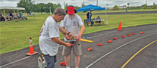
Great Planes motors are sold under the ElectriFly brand name. They feature plug-and-play electric-power systems for models weighing 5 ounces to 50 pounds.
Controlling Speed
Running at partial throttle is merely a more complicated case of running at full throttle. Instead of leaving two FETs (positive and negative) on for the entire period of the motor pole’s transit of the motor winding, one is turned on, while the other is rapidly pulsed on and off to reduce the average power seen in the winding. At low throttles this second FET is barely on, but it is on almost the whole time near full throttle. The frequency (times per second) at which we pulse the power for speed control—not the polarity switches that drive the motor—is called the PWM rate, or switching frequency. One of the paradoxes of brushless-motor controllers is that partial throttle operation generates more ESC heat than full-throttle operation. FETs have a small resistance when they are fully on and current is flowing through them. This generates a relatively little amount of heat. As always, there’s more to it. FETs don’t simply go from an on to an off state; there is a bit of a ramp to the process in which the FET is neither open nor closed. Electricity can flow through the FET during these periods, but the resistance in the FET is much higher than when the FET is fully on. This leakage across a high resistance generates a significant amount of heat.
Plug-and-play systems are noted for their ease of use—no soldering. Electric-power systems from E-flite are that easy and are labeled with a system that correlates with glow-power designations.
At partial throttle, FETs are required to cycle much more rapidly than at full throttle, so a great deal more heat is generated at partial throttle than at full throttle. Similarly, more heat is generated in controllers set to run at high switching rates than those set to run at lower switching rates.
Hardware Voltage Limitations—4S, 6S, HV
Brushless ESCs are generally rated for a specific range of voltage. This is due in part to the voltage rating of the FETs themselves. Generally, higher-voltage FETs are usually more resistive than lower voltage FETs, so higher-voltage controllers will require more FET capacity than lower voltage controllers to handle the same amount of current. The drive circuitry must also be modified to handle the higher voltages. The FET voltage limitation is a hard number. Exceeding the FETs voltage limit usually results in instant destruction of the FET. Always pay attention to the voltage limits recommended by the ESC manufacturer.Hardware Amperage Limits—10 amps, 25 amps, 35 amps, etc.
Unfortunately amperage limitations are not always blackand- white. A number of considerations determines the current an ESC can handle successfully. There is a current above which the silicon inside the FETs or the metal legs or connections on the FET break down and fail. Damage from excessive amp draw takes place in an instant.
AXi motors can arguably be credited with making electric power available via mass production and reasonable pricing. They are among the most efficient systems available.
Think of a fast-acting fuse, except that an ESC is seldom considered to be expendable. It is difficult to anticipate high currents and shut down the controller in time to prevent the current spike from damaging the controller. Partial throttle operation generates more heat, as does high PWM rates. The amperage capability of an ESC is limited by the ability of the device to dissipate heat generated by the resistance of FETs and circuit boards. If a controller is making more heat than it can dissipate, a “runaway” condition occurs. This can lead to thermal destruction of the controller; solder holding the components to the boards literally melts, and the parts are free to float away. A great way to rate a controller is to determine its “steady state amperage.” That is the maximum current it can carry at its rated voltage without experiencing further temperature rise. This can vary a bit, because the temperature rise depends on ambient air temperature and the amount of cooling airflow over the ESC. A dangerous way to rate a controller is to state its “surge” or “burst” capabilities. These indicate that the controller might be able to handle higher currents for short periods, but those periods are sometimes shorter than the pilot would hope. That is another area in which manufacturers can rate their products based on their own, often ridiculous, definition of a controller duty cycle. Read the fine print. Like the proverbial duck on water, things look calm on top but there’s a whole lot going on inside a brushless motor controller. A great deal of engineering goes into the physical design, and the software is surprisingly complex. Always use a power system inside its performance envelope for best performance and reliability. -Lee Estingoy [email protected]


Comments
Acronyms
Great article, great explanation. Could use better definition of all the acronyms, maybe even a glossary for use in future similar articles. E.g., "PWM rate" is probably Pulse Width Modulation rate, and rather than defining it as switching frequency should have been spelled out and better defined. Also a few values, e.g., typical capacitor size, and voltage traces off of an oscilloscope, rather than calling it "ripple", would be helpful. However, again Great article and explanation.
Great introduction to
Great introduction to brushless ESCs. Please keep it up with other topics.
Thanks
Thanks
inside the speed control
Great insight into the inner workings. Is there more to come? How the programs are written and how they limit the speed controller would be interesting.
Great Article.
Great Article.
Very Interesting
Very Interesting
poorly written
Let me be blunt. I am an electronics textbook author. The author of this article may know his material, but this article is dreadful. Some places he is just plain wrong. Does anyone edit these articles? As an expert in electronics, even I have difficulty understanding what the author is trying to get across much of the time.
I am new to the world of
I am new to the world of electric powered model aircraft and found this article very informative. This is the kind of information that cannot be gotten from a sales person at your local hobby shop.
Very good article. I had not
Very good article. I had not considered, but it makes sense, that the heat generated at partial throttle is higher than full throttle. I always try to use an ESC that has a current rating that is, at least, 20% higher than the maximum current from the chosen motor/propeller combination.
Inside the Electronic Speed Control
Most of this electronic talk is way over my head. One huge problem I have in this article is the use of "controller" and "ESC" in the same sentence or interchanging those terms. It's confusing and if they are both the same, then please do not interchange those terms -- or did I miss something?
I'm glad you touched on the heat problem when using partial power. Would it be better to install a larger-than-needed ESC, or is there a down-side to that other than the weight?
Thanx
Brushless motor control
And here all along, I thought an ESC was just an empty shell.
I found the article clearly written and easy to understand. I would like to see more of this type of writing, particularly as it applies to helis and multi-rotors.
VERY HELPFUL!
VERY HELPFUL!
Add new comment