
Written by David Buxton
An overview of the inner workings of 2.4 GHz technology
Technical
As seen in the February 2015 issue of Model Aviation.
Go to a regional fun-fly or national event to watch airplanes and helicopters fly without the need of a frequency board. You have to wonder how it works. Is it true that the full 80 MHz wide 2.4 GHz band can support as many as 200 airplanes? If you are like me, you are not willing to accept that several radios can share the same frequency until you understand how it’s done.
This article has evolved considerably—woven with popular theories and explanations that each were found to be incorrect. Too often, the correct information is buried in theoretical formulas that few of you would care to understand. The objective of this article is to present the theory of how our RC radios work in an easily understood format.
Manufacturer
Marketed Technology
Futaba
FHSS
Futaba
FASST
Spektrum/JR
DSM
Spektrum/JR
DSM2
Spektrum/JR
DSMX
JR
DMSS
Hitec
AFHSS
Turnigy
V1
Turnigy
V2
Airtronics
FHSS-x
Wi-Fi
2.4 GHz Spread Spectrum
The following are three important technologies used by our 2.4 GHz band radios. It is a frequency band that is increasingly popular for a growing variety of commercial products: • Frequency Hopping Spread Spectrum (FHSS): Transmitter and receiver hop in unison to a mutually common pseudo random sequence of frequencies. One or more packets of data are transmitted before each hop. • Direct Sequence Spread Spectrum (DSSS): Digital sequence modulation applied to the carrier frequency. It looks like noise on a spectrum analyzer and is the recommended form of modulation used by FHSS for transmitting data. • Cyclical Redundancy Code (CRC): A key premise is that data sometimes becomes corrupted. The transmitter’s and receiver’s CRC calculation won’t match if one part is slightly off. RC receivers ignore flawed packets, but Wi-Fi asks for a retry.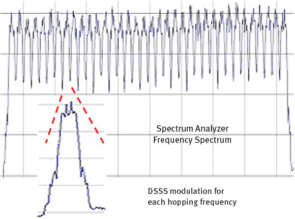
80 MHz wide 2.4 GHz band 36 frequency hopping channels. FHSS with DSSS modulation.
Futaba’s first 2.4 GHz RC radios started out with modulated FHSS, and later models added DSSS, which was introduced as Futaba Advanced Spread Spectrum Technology (FASST). Spektrum’s DSSS-only system (no hopping) was introduced as DSM, which was later enhanced with hopping frequencies called DSM2, which was followed by DSMX.
CDMA
Code Division Multiple Access (CDMA) is the DSSS technology used by our RC radios. It is designed for several radios on the same frequency. Figure 2 illustrates how each data bit is expanded using several encoding bits. Note that the encoding pattern for a ‘0’ data bit and a ‘1’ data bit are mirror images of each other.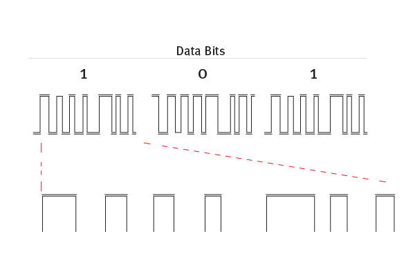
Figure 2: A direct-sequence CDMA encoding pattern.
The higher the ratio of coding bits for each data bit, the better the DSSS process can extract data from noise. The ratio is referred to as process gain (which will be illustrated and explained later). RC radios use a higher process gain than Wi-Fi. Both DSSS-encoded signals can travel as far, but our radios can extract clean data packets at a greater distance than Wi-Fi. Here are three process gain examples that help explain a key benefit of DSSS: • Most (perhaps all) Wi-Fi uses a process gain of 11. The range is roughly 850 feet outdoors. • Transmitters use 64-bit CDMA codes. Range can be up to 2 to 3 miles or more, depending on factors such as power output. • GPS (not 2.4 GHz) has a process gain of 1024. Satellite altitude is 12.6 miles and the distance is farther near the horizon. GPS satellites use a common frequency for the 24 to 32 US satellites that employ different DSSS codes without frequency hopping.
Communicating Edges
It is important to understand that CDMA communicates the edges of each coding bit and not the high or low levels. This section will help you understand how it works. Those with an electronics background understand the relationship between rise time and bandwidth. The faster a signal shifts from one level to another—the wider the spread of harmonics and the wider the bandwidth. The same thing happens if a signal shifts between two frequencies or shifts between two phases (e.g. 180°, 90°) of the same frequency. The faster the shift, the wider the spread spectrum’s bandwidth. There are spread spectrum shift key technologies that accomplish CDMA edge modulation by shifting between two frequencies—two or four phases or amplitudes. Figure 3 illustrates shift keying. Each rapid shift results in a narrow pulse of spread spectrum energy that looks like noise with a frequency response spread as seen on a spectrum analyzer.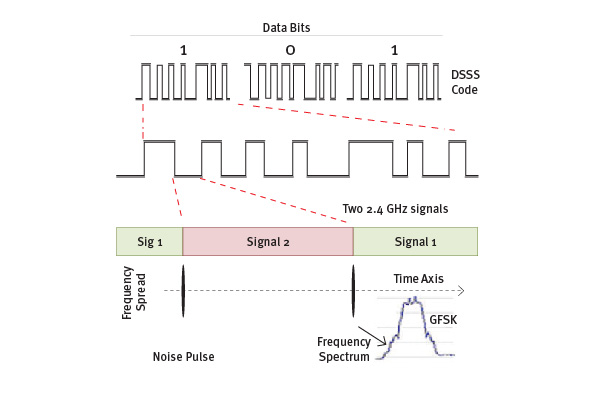
Figure 3: Shift key modulation.
Most of our RC radios use Gaussian Frequency Shift Keying (GFSK). Gaussian specifies the type of shaping filter used to translate the shift keying into spread spectrum. The Gaussian filter optimizes performance while reducing the bandwidth. In this case, less bandwidth can be a good thing.
Receiver Decoding
The CDMA illustration (Figure 4) is applicable for the different forms of shift keying. A multiplier circuit is fed with a pattern of 0s, 1s, and -1s timed by the DSSS code series used by the transmitter. Figure 5 uses an illustratively short DSS code.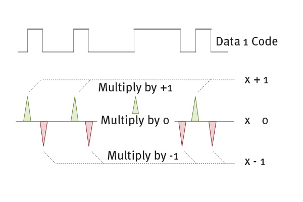
Figure 4: Decoding phase modulation data.
Most of the time, the incoming signal is being ignored because it is being multiplied by zero. Two radio systems out of sync with each other will not “see” each other. A phase lock loop (PLL) plays a vital role in keeping your receiver’s 2.4 GHz clock in sync with your transmitter’s clock. The PLL acts like a flywheel to keep the receiver’s clock on track until the next edge is detected. The PLL speeds up or slows down to accommodate Doppler shift.
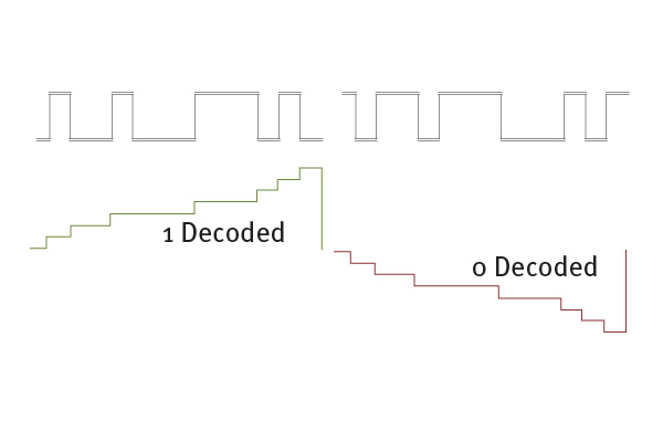
Figure 5: Translating code bits into data bits.
The output of the multiplier circuit connects to an integrator that accumulates the sum of each edge. The longer the series of coding bits, the higher the staircase will rise or descend for a final determination at the end of each data bit series. A successful decode is accomplished as long as the final summation is correctly positive or negative. The crude simulation in Figure 6 uses a 64-bit DSSS code and noise that is more than 200 times stronger than the signal.
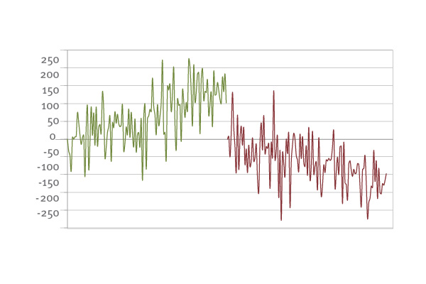
Figure 6: DSS code with noise simulation that is more than 200 times stronger than the signal.
The number of bits in the DSSS code pattern is referred to as process gain. Increasing the gain increases your receiver’s ability to lift your transmitter’s faint signals out of the noise at a considerable distance. It also helps to separate your radio’s signal from that of other radios that may have hopped to your radio’s current frequency. CDMA timing and process gain make it possible for several radios to share the same frequency. This explains why 2.4 GHz microwave ovens and basic Wi-Fi are not a threat. There are 2.4 GHz commercial products that can menace our radios. One of the most threatening examples is a high-powered 2.4 GHz non-spread video link using a high-gain or narrow-beam antenna. A growing number of imported products are advertised as exceeding FCC regulations. These threats are the compelling reason for FHSS.
A Closer Look
This section, with its superficially explained alphabet soup, is for those who would like to dig deeper than this article. These are the integrated circuits (ICs) that our radios use: • Micro Linear ML2724 used by Futaba FASST. • Cypress CYRF6936 used by JR/Spektrum’s DSM, DSM2, and DSMX. • Texas Instruments CC2500 used by Hitec, Corona, FrSky, Tactic, Futaba S-FHSS, and Wi-Spy’s USB spectrum analyzer. • Texas Instruments CC2520 used for JR’s DMSS. These are ICs designed for commercial applications. The radio manufacturers’ patented features are coded into the central processing unit and microcontrollers, such as the example in Figure 7. The first three ICs listed use GFSK modulation and are used in consumer products such as cordless phones, wireless keyboards, and game controllers.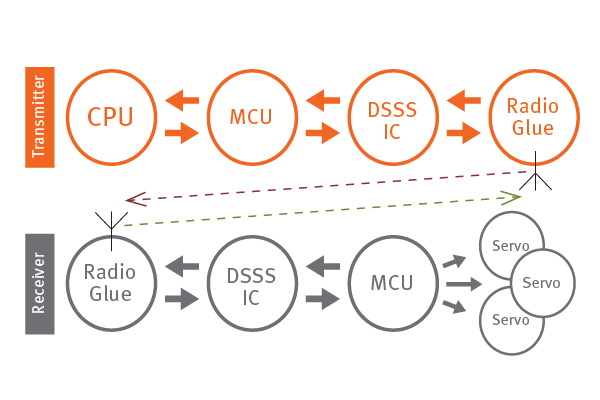
Figure 7: Micro controller unit DSSS integrated circuits.
Some model aviation enthusiasts use these ICs to build and program their own radios. Some participate in the FrSky open-source project.


Comments
Great article with a misprint.
GPS satellites are at about 12,500 miles, not 12.6 miles.
GPS Satellite altitude
Your article states 12.6 miles... I believe it is actually 12.6 THOUSAND (about 12,550 miles).
GPS satellite
GPS satellite altitude is about 12,600 miles, not 12.6 miles !!
Would like to have this sent
Would like to have this sent to my email as well as an AMA member I would appreciate getting more material through email thank you
Here's an extremely better explanation of CDMA
https://www.youtube.com/watch?v=XJ81CuujwYE
Good article but most will
Good article but most will not undestand it.
You forgot the best one!!!
Looks like you overlooked FrSky's AACST on your list of frequency hopping radio tech. Arguably the best of the pack!
The GPS SV are 12,550 Miles
The GPS SV are 12,550 Miles up not 12.6 Miles. A slight slip of the deciamal point.
I believe the altitude for a
I believe the altitude for a GPS satillite is 12.600 miles not 12.6 miles as is shown in the article
RC de-mystified
It's all just magic....
SPREAD SPECTRUM ARTICLE
Can you comment on JR/DMSS "wider grip" chart discussing their modulation.Techies say it is the strongest.Thinking about going DMSS --just want to be sure it is the right move. Thank You MARCY
"GPS (not 2.4 GHz) has a
"GPS (not 2.4 GHz) has a process gain of 1024. Satellite altitude is 12.6 miles..."
Try 12.6 THOUSAND miles.
http://www.gps.gov/systems/gps/space/
Add new comment