
Written by Walt Wilson
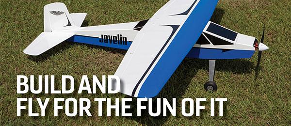
Create exactly what you want, for the fun of it
How To Do It
As seen in the April 2011 issue of Model Aviation.
Scratch-Building Essentials
To build from scratch, or even from a kit, you need several basic tools. A hobby knife set is necessary for any building project—even assembling ARFs. Inexpensive sets are available almost anywhere hardware and crafts are sold. If you want better quality, purchase an X-Acto set from your local hobby shop. You can use others, but a #11 blade will be the most used; stock up with lots of extra blades. They’re available in packs of 100 for a good price, and you’ll use them if you build much. In addition, they dull quickly when cutting MonoKote and similar covering materials. Every household, even if it has no model builders in it, should have an electric drill. Cordless drills are convenient and versatile, but the good ones can be expensive. And if you don’t charge them after use or keep them on a trickle charger, the batteries tend to run down when you need them most. Many cordless drills can be used as forceful screwdrivers too. Although it is a bit more trouble, you can also use a drill with a cord. It is generally less expensive and always ready when you need it. Obtain a drill press if you can afford it. Many are inexpensive and have amazing capabilities besides making accurate-size holes that are perpendicular to surfaces. A drill press can be adapted to use as a milling machine, sander, lathe, and probably some other things. A set of hole saws will prove to be valuable. Those are available at most stores that sell woodworking tools. A Dremel, or equivalent, power tool has all kinds of uses and is an important part of any shop. Cutoff wheels and sanding drums are indispensible. Most plywood and thicker balsa parts can be cut with a basic coping saw, but it’s much easier to use a band saw or a jigsaw. The latter will do most small jobs, but I much prefer a band saw with a metal-cutting blade. The metal-cutting blade allows you to cut aluminum for landing gear, gear covers, and other applications, as well as all types of wood. Other helpful tools are bench-type belt/disc sanders and, if you plan to carve much balsa, Great Planes Power Planers. There are many good-quality brands of power tools. The Sears Craftsman line is competitively priced. Since you’ll probably find uses for these tools far beyond modeling, get the biggest (within reason) and best you can afford. It’s unnecessary to have all of the equipment I’ve mentioned just for building models, but it does make it easier. Hand tools can be used for most applications. Okay, let’s cut some wood!Scratch-Building
If you've accomplished building model aircraft from kits and want to go a step further, try building from scratch. There’s a lot of satisfaction to be gained from constructing an airplane from a pile of balsa and plywood. The major reason for scratch-building is to have something unique. Don’t worry if you’re not an aerodynamic wizard; borrow from an established design. Producing a model from plans and converting a glow-powered design to electric can be a good start. “Quarter Midgets,” or .15-size sport aircraft that were popular in the 1970s, can be great designs to convert to electric power. Plans for many of them are still available from magazine plans services.Image

The scratch-build method in this case was to reduce and paste up plans of a favorite kit of a larger model. Not all kit plans are complete, so prepare to exercise your imagination.
Reducing a large favorite aircraft and converting it to electric power or a different size glow engine can also be a good first project. And it isn’t as difficult as it might sound. If a complete kit or set of plans from an old kit is unavailable, check with fellow club members who build their own aircraft or purchase plans from your favorite aeromodeling magazine or plans seller. Plans for some kits that became popular were first published in modeling publications. Decide what size you want the airplane to be and what power system you’ll use. A 36- to 40-inch wingspan is nice for electric or .15-.25 glow power. That size of model is big enough to fly well, and the components can usually be fitted with little difficulty. Aircraft in that size range are easy to transport too, if you don’t have a van, SUV, or other large vehicle. And in most cases, the cost of electric power components won’t break the bank. Use a copy machine at the local office supply store to modify the plans to the size you want. Use 11 x 17-inch paper. You can also resize plans with a scanner attached to your home computer, but scaling could be more difficult and the printing size is usually limited to 81/2 x 11-inch paper, requiring many more copies. The reduced plans set will be in pieces, so line up and overlap the segments, and be sure that all major parts are shown. Then trim and tape the pieces together with outlines and centerlines aligned, and mount them on a piece of white cardboard, or poster board. You can get it from most dollar stores or art-supply shops. Now you need a piece of vellum, or similar translucent paper, that is large enough for the project. This kind of paper is available at artsupply stores. Tape the vellum over the plans. If you want to modify anything, such as the shape of the fuselage, wingtips, or tail surfaces, now is the time to draw the changes. If you want a more aerobatic model, such as for 3-D flying, examine the relative sizes of control surfaces on aircraft that are capable of the maneuvers you want to do; increase or adjust your design’s surface sizes appropriately. Trace the significant parts, and sketch any details you might want to change.
Image

The author admired the Sig Four-Star design so much that he wanted a version that would be suitable for small-field flying.
Begin construction with the fuselage. Determine the thicknesses of balsa, plywood, or other materials to be used. If the model will have electric power, most parts can, and for weight savings should, be somewhat lighter than those used for glow power. The firewall, or engine-mounting structure, should be plywood, but it can be thinner than is normally used for a glow engine. You can typically replace non-load-bearing plywood bulkheads with balsa. Measure your components, such as motor, battery, ESC, servos, and receiver, and figure out where they will be located. If necessary, add, remove, or change the locations of formers to accommodate the components. Formers can ordinarily go where the original design has them. The motor will usually be in the front (some models are pushers), so measure the distance from the propeller drive surface to the back of the mounting plate for your motor, and add roughly 1/16 inch. That’s how far the firewall must be from the front of the fuselage. Formers are normally required at the front and back edges of the wing. They have to bear loads, so they should be plywood. Landing gear mounting blocks and related bulkheads should also be plywood. Most motors are fairly lightweight, so the battery must be placed as far forward as possible in the fuselage for balancing. Is the forward fuselage large enough to accommodate the required battery? If not, modify the height or width so it will be. If possible, provide space to move the battery fore and aft a bit to aid in balancing. Provide for passage of cooling air for the motor, ESC, and battery while developing your design. Most plans sets show the formers and wing ribs, so tracing the outlines is easy enough. If formers are not shown or must be moved fore or aft, measure the height and width of the fuselage in each location and then adjust dimensions as necessary. Consider what size holes must be cut in the formers to accommodate components, pushrods, etc. The formers can be figured out fairly easily, based on making everything fit. If you want rounded corners on the fuselage, add pieces of triangular stock to the appropriate areas. Trim the corners of the formers to accommodate the triangular stock. The wing saddles usually need additional thickness or reinforcement, so add thin plywood or an extra, thicker layer of balsa in those locations. The firewall and landing gear mounting can normally use reinforcement too. On the Sig Manufacturing Four-Star replica shown, the 1/16 plywood reinforcements run from the former at the TE of the wing to the back of the firewall; they are used for supporting the landing gear mount. The firewall is 3/16 plywood, and the other formers are 1/16 plywood. The fuselage sides and miscellaneous parts are 3/32 balsa. Once you’ve adapted and redesigned to your satisfaction, it’s time to cut wood. Trace the parts onto the appropriate material and cut out all required parts, to make a “kit” before assembly. I’ll address building in the traditional manner, with balsa, spruce, plywood, etc.
Image

Scratch builders make a kit before starting assembly. Dry-fitting the parts can help detect design flaws before glue makes the errors permanent.
Cut out most of the parts needed before starting construction. Trace or lay out the fuselage sides on a piece of balsa in the desired thickness. Some models, such as those in the Four-Star series, have formers keyed to the sides of the fuselage. It helps to install the formers straight if this feature is used when building a spin-off. Tape another piece of balsa to the fuselage side marked for cutting, and cut both sides at the same time. This assures that they are the same. Use a band saw to cut the slots for former tabs. If you want lightening holes in the fuselage sides, hole saws can be used to cut the ends and an X-Acto knife to cut between the holes. Trace or otherwise lay out the formers on the appropriate thickness of plywood or balsa. Most formers will require holes for the battery, ESC, wires, pushrods, etc. If the wing LE will be held in place with a dowel, or center rib extension, now is the time to cut or drill that hole. Cut out the landing gear mounting block if it will be installed in the fuselage.
Image

A frame with flat sides is an excellent choice for a first-time scratch-build project. Because this model borrows its de sign from a kit, the assembly instructions can be helpful.
It’s usually safest to drill or cut all required holes before cutting the former outline, because larger pieces of wood are easier to hold and less likely to break. If the hole is to be essentially square, drill small holes at the corners and use a Dremel cutoff tool or coping saw to cut between the holes. If holes are to be round, use the nearest-size hole saw. Remember that this is your design, so you can take liberties where necessary. Clean up any rough edges or adjust hole sizes with a sanding drum in a Dremel tool. Locate the centerlines (vertical and horizontal) for the motor on the firewall, and lay out the pattern for motor mounting holes. If there will be offsets, plan for them now by offsetting the centerlines so that the propeller drive hub will be centered when the engine is installed. Drill the holes and install blind nuts before installing the firewall in the fuselage. Allow for passage of any wires through the firewall to the ESC. If you’re building an electric model, provide for intake and egress of cooling air for the ESC and battery. If you’re using a glow engine, locate and drill holes for the throttle pushrod and fuel lines, or tank plug, now. It’s easier to do all this before installing the firewall.
Image

Scratch-building requires provisional thought. In this case, air passes through the corners of the square fuselage to cool the motor and electronic components.
The type of airplane you have chosen will dictate building procedures. With the 60% Four-Star replica, when laying out the formers for the fuselage, I was sure to mark top-to-bottom centerlines on all of them. If you plan to round the nose or other areas, install triangular stock at the top and bottom of the sides. Start assembly by gluing doublers, wing saddles, triangular stock, etc. to the fuselage sides. Be sure to make a left and a right side. Install the formers at the front and rear of the wing. The fuselage sides are usually parallel in this area, so mounting the formers perpendicular to the sides is easy enough. Lay one side flat on the building board and glue the formers 90° from the side. When dry, cured, or whatever, depending on adhesive type (I recommend one that dries slowly for this operation), adhere the other fuselage side in place on the other side of the formers. Carefully maintain the 90° angles, ensuring that the sides are parallel to each other and the ends are aligned. If your model has slots and tabs, as the Four-Star series does, alignment is easier, but check it again before it dries to be sure. When the center formers are secure, lay out a centerline on your building board. Position all aft formers while pulling the tail end together. Line up all centerlines on the formers with the centerline on the building board. It helps to put heavy weights on each side of the previously assembled center part of the fuselage, to hold it in place. Make sure that the fuselage sides are aligned, vertically and horizontally, at the aft end. When satisfied that all parts are centered, use CA or your preferred glue to install them. Repeat the procedure with all forward formers except the nose ring (if you have one), being careful to align the centerlines.
Image

Fuselage designs with flat sides make it easy to bui ld a square structure. All formers are perpendicular to the long fuselage side.
If engine offset is planned, make sure that you install the firewall at the necessary angle to provide it. I prefer using epoxy for installing firewalls. When the glue is dry, cut out and add the servo trays, battery tray, landing gear block, cockpit floor, and any other internal structure. These parts might be provided in a kit but not detailed on the plans. They can be cut to fit in most cases, preventing bad fits caused by tolerance buildup, etc. For easy access I installed the rudder and elevator servos and pushrod tubes before sheeting the bottom of the aft fuselage. In the 60% electric-powered Four-Star, the Hitec HS-55 servos are mounted in the same general location as those in the larger Four-Star 40s. Determine where slots or holes for rudder and elevator pushrods should be, allowing for the lengths and locations of control horns. I used .043-inch-diameter music-wire pushrods inside plastic tubing, supported on both ends and in one location in the middle. Add stringers to the aft fuselage deck or other places where applicable. Install any remaining formers, and sheet the upper fuselage as required with 1/16 balsa. Install all battery and ESC shelves, the landing gear mounting block, and blind nuts before sheeting the bottom of the forward fuselage. You’re close to 50% finished with construction. Build and install the wing before sheeting the bottom aft fuselage, to assure a good fit.
Image

Another good tip for new scratch builders is to choose a straight wing design. That way, multiple ribs can be made simultaneously. Tapered ailerons simulate a more advanced look.
A question I had was, When scaling down a wing, how do you know what size spars to use? The answer is to scale them down too. The original Four-Star 40 has 3/8 x 3/16 spruce spars. Electric power is easier on structure than an engine, so 3/16 square hard balsa should work for the main spars. Four-Stars have five spars, so all but the main spars, top and bottom, could go down to 1/8. I used those sizes on my airplane, and they worked fine. The ribs are 1/16 balsa; 1/32 would work but is extremely fragile. Use the reduced-size rib outlines to determine airfoil and spar placement. I used rib spacing that was close to that of the full-size Four-Star 40 and decreased the number of ribs to save weight. Make two templates from 1/8 plywood for cutting ribs. Drill holes and use 3/16- or 1/4-inch-diameter dowels to hold the templates and balsa together. Trace the rib outlines onto balsa, and use an X-Acto knife to cut all ribs a bit oversize. Assemble all of the same-size balsa ribs between the plywood templates, drill, and hold together using the dowels.
Image

Typical cutting implements used for model building include (clockwise from top) an X-Acto razor saw, a hand plane, a bulk pack of #11 X-Acto blades, a hobby knife, a single-edge razor blade, and (center) a balsa stripper. Carelessness with any tools can land you in the emergency room.
Sand all ribs to the exact shape and cut notches for spars at the same time, using the templates as a guide. All W-2 ribs should be identical at this point. The W-1 ribs are 1/8 inch thinner (11/16 on each side), to allow for the 1/16- inch center sheeting. Cut a joiner from 3/16 plywood (or the same thickness as the main spars), and cut 1/16 balsa to width for the TE sheeting. Make a scaled-down LE from medium balsa. Cut a TE to size and sand to a slight taper to match the TE sheeting. Glue the ribs and spar parts together with CA. Be sure to make left and right wing panels, and cant the center W-1 ribs, as shown on the full-size plans, to allow for dihedral. Add 1/16 balsa shear webs on each side of the main spars in the area to be sheeted on each panel; shear-web grain should be vertical. They make a box to contain the wing joiner. Cut out the area between the main spars in the center ribs to accommodate a wing joiner. Check the fit and try pushing the wing halves together, with the joiner in place, before gluing. Sand and trim the joiner as necessary to make it fit. Place proper-thickness wood blocks under the tips for dihedral and join the wing halves with 30-minute epoxy, ensuring that the wing tips are in alignment with each other. Determine where the wing-mounting screws will be, and make sure that there is solid balsa in that area. Add balsa blocks if necessary. Add 1/16 sheeting to the center of the wing where shown on the plans. Make ailerons from 3/16 balsa sheet and sand them. Sand a “V” shape on their LEs, to provide clearance for movement when hinged. If the ailerons are significantly larger, for 3-D flying, consider building them using the technique I will describe later when I address the tail surfaces. The easiest way to make tail surfaces is to simply cut them from 3/16 or 1/8 balsa.
Image

The author suggests an excellent tail-surface construction method. The fin and stabilizer are built up using laminated 1/16 balsa. Lightening holes can be cut in the core sheet after assembly, if desired.
Sand them smooth, and sand a “V” shape on the LEs of the elevator and rudder hinged edges. If you want lighter surfaces, an open built-up structure will do the job. I have a slick way to make a light structure. Check (look down the edges) and buy balsa that is unwarped. Cut pieces of 1/16 balsa to the desired shapes for the fin, stabilizer, rudder, and elevator, with the grain running lengthwise. Make doublers for areas where the control horns and tail wheel tiller will be located. Make a doubler for the center of the stabilizer that is approximately 1/4 inch wider on each side than the fuselage at that point. Select proper-thickness balsa strips to make the surfaces the thickness that you want. They’re available in most sizes from your favorite hobby shop. If you cut your own, use a balsa stripper to make the pieces the desired width to make LEs and TEs. With the balsa core on a flat surface, use thin CA to glue the doublers in place. If the edges or tips are curved, sometimes you can use the scrap from cutting the original outline as a doubler, at least on one side. Cut more strips to make ribs, perpendicular to the core grain, and glue in place with CA. How many ribs do you need? I used two on each side for the 60% Four-Star. Space the ribs evenly and use what looks right; it’s noncritical. Repeat all the doublers and ribs on the other side (bottom) of the core. The CA hardens the balsa, making a plywoodlike structure, and, under normal atmospheric conditions, the perpendicular wood grains keep it from warping. Sand the edges to the desired shapes. If a knife edge is desired, install ribs and sand to a taper, but don’t use a doubler on the outer edge. If you want, use a Dremel tool and sanding drum to cut lightening holes in the cores after assembly. Sand the rudder and elevator LEs to a wedge shape and cut slots for hinges. I use the Great Planes Slot Machine for this, but a knife or purpose-made slot cutter can also do the job.
Image

The Great Planes Slot Machine (top) cuts hinge slots, and the Great Planes Power Planer shapes solid-wood parts. Both are useful for the scratch builder and can cause bodily injury if used improperly. Be careful!
If you want a different-thickness surface, use different-size doublers and ribs, but stay with the 1/16-inch core unless you’re building a much larger aircraft. Sand all surfaces smooth, and cover the mating surfaces to be hinged with strips of covering material that is roughly 1/4 inch wide. Then cover the rest of the surfaces, overlapping the strips and edges. Install CA-type hinge material and you’re finished. This building technique can be used for much bigger airplanes too. It makes a lightweight yet strong and rigid structure, and it is almost as quick to build as it is to describe. Cut and install wing-mounting blocks in the fuselage. Make them large enough to have sufficient wood around the bolt locations, but leave room between them for the aileron control rods and horns. Install the blocks approximately 11/16-1/8 inch below the aft wing saddle surface. Cut a piece of dowel rod close to 1 inch long and, chucking it in an electric drill or drill press, sand one end round. A 3/16- inch-diameter dowel will work fine for a small electric airplane; you could enlarge the dowel to 1/4 inch for a glow-powered aircraft. Drill and install the wing retaining dowel in the center of the wing LE, with the rounded end out. Fit the wing in the saddle and be sure that it properly fits the contour. Adjust the dowel hole as necessary for a good fit. When you’re satisfied that it’s correct, glue the dowel into the wing. Put the wing in place and align it by measuring from each wingtip to the center of the aft end of the fuselage. Determine the wing-mounting-bolt locations. With the wing properly aligned, with an equal measurement from each wingtip to the center of the fuselage tail end, drill the bolt holes. I used two 4-40 screws, with flat washers, to hold the wing in place on the little Four-Star. Once the holes are located in the mounting blocks, drill as necessary and install blind nuts. With the wing installed, fit and sheet the aft fuselage bottom with 11/16 balsa, with the grain crossways. Use fine sandpaper to smooth all surfaces, corners, edges, and irregularities in the fuselage and wing. Instructions are included with most covering materials, so I’ll address that part in general.
Image

This is what is called the “bones” shot. The exposed wood is ready for final sanding in preparation for covering.
As with the tail, cover the mating hinge surfaces with narrow strips of your favorite iron-on material. Cover the wingtips, with some overlap around the edges, and iron it smooth. Cover the bottom of the wing, one side at a time, with some material overlapping the edges and roughly 1/2 inch of overlap in the center. Ensure that every edge is tightly sealed before shrinking the center of the material. Pulling edges loose can be a problem if you don’t. Trim any excess with a new #11 X-Acto blade. Cover the top, one side at a time, with some material overlapping the edges and close to ½ inch of overlap in the center. Trim as necessary and iron down all loose edges. Cover the rest of the ailerons, first on the bottom and then on top. Cover the bottom surfaces of the fuselage, with some overlap around the edges. Cover the sides and then the top surfaces.
Image

Building leads to finishing. A small model such as the author’s was covered in Solite to save weight. Models with wingspans longer than 40 inches can be covered with MonoKote or UltraCote.
You should have made slots in the balsa for the stabilizer and fin when you cut out the sides of the fuselage. On the miniaturized Four-Star, the stabilizer is installed on a flat surface on top of the fuselage. Trim away the covering material in areas to be mated with the stabilizer. Horizontally align the stabilizer with the wing by measuring tip to tip. The stabilizer can be held in place with pins or rubber bands while checking alignment. When you are satisfied, use a felt-tip marker to sketch the outlines of the fuselage edges on the stabilizer. Trim the covering on the stabilizer so that the joint to be glued is wood to wood, with just enough covering overlap to hide the joints. Vertically align the stabilizer by sighting from aft of the tail and comparing the stabilizer tips with the wing. Trim or shim the fuselage as necessary to get it right. The better the alignment, the less likely your model will be to have weird flying characteristics. Install the stabilizer using CA or your favorite adhesive. Trim the covering as necessary and install the fin 90° from the surface of the stabilizer. Be sure that the aft fuselage and back of the fin are aligned for rudder hinging. Commercially made aluminum landing gear is available from most hobby shops, but the chances of finding a set that perfectly fits your airplane are slim. You can fabricate landing gear from .062-inchdiameter sheet aluminum cut out on a band saw with a metal-cutting blade. File and sand the edges smooth, and bend it into shape using a drill press vise. If the vise jaws are rough, protect the aluminum with scrap sheet metal to keep from marking it. If a buffer is available, polish the aluminum. You can also make landing gear from music wire.
Image

Drill press vises have many applications in aeromodeling. The author made the one shown in a high school shop class, and it has had many years of hard use. Manufactured drill press vises are available for as little as $9.95 at Harbor Freight.
Look for lightweight wheels in a size that looks appropriate. I fly from an asphalt runway, so 1 1/4-inch-diameter wheels work fine. If you fly off of grass, you will probably need to use bigger wheels. The first two Four-Star replicas I built had open wheels. The most recent version has scratch-built wheel pants. A variety of hobby shops sell canopies for numerous sizes of models. The ones I used on my aircraft were cut from a World War II 9-inch bubble canopy from Sig. You could also use plastic soda or water bottles or various product bubble packs as canopies. From this point forward, assembly is essentially the same as with a kit-built model. Install the motor, ESC, and radio. I’ve used a full-size, full-range Futaba receiver in all three Four-Star replicas I’ve built.
Image

A variety of manufactured and homemade clamps may be used. One-inch-square wood blocks with nails are easy to make and useful for holding structures in place on a building board. Manufactured clamps are available from Harbor Freight and other tool sellers.
My current model has a Rimfire 28-30-950 motor, E-flite 25-amp ESC, Hitec HS-55 servos, and 3S 11.1-volt, 2100 mAh battery. This sized-down Four-Star 40 has an all-up weight of 24 ounces and flies similar to the full-size version. Even moderate winds are no problem. Start with the CG in the same relative place as on the airplane you used as the source for your design. Shift the battery fore or aft, if possible, to aid balancing before adding weight. I had to put 1/4 ounce of lead in the tail of my current aircraft. I didn’t have to add weight to the previous versions, but they used lighter batteries and smaller ESCs, and they weighed 20 ounces apiece. When in doubt, go slightly nose-heavy—never-tail-heavy—and your new model will be more likely to survive for a second flight. Scale down the source airplane’s recommended control surface throws. Use an incidence meter or other method to assure that when the trim is centered, the ailerons are in equal positions at the outboard tips before flying. That will reduce the likelihood of unpleasant surprises on the first takeoff. Have fun with your new scratch-built model! It will give you much more pride of accomplishment than any ARF. Once you have completed your first scratch-built airplane, you might want to move on to more elaborate, more original projects. The sky’s the limit! -Walt Wilson [email protected]


Comments
This looks very challenging ...
I learned to build my first kit last winter, with much assistance to learn how to do things. This looks very challenging!!
One really good source for
One really good source for old plans is
the outerzone in the UK.
Building boards
I didn't see any mention of cutting or building boards. X-Acto and others make a cutting mat that keeps the cutting knife steady while cutting the part. Homasote makes a good surface to push pins in to hold the parts on a building board.
Aluminum Landing Gear
Thanks for the article. I have begun a scratch build which requires custom landing gear.
You mention fabricating aluminum landing gear. Where can you find the right type of aluminum, and how do you strengthen the bends?
Scratch build
This is not scratch building. This is building from plans. A scratch build is built from plans you have drawn. Would expect am AMA article to know the difference?
I replied the same with a bit
I replied the same with a bit more detail before seeing your comment. Odd indeed this was not caught...
Scratch build mentioned in article
Scratch build is creating or drawing your own plans for your own design or of an actual aircraft which doesn’t current exist in plan form. Build from plans is called a plans build or building from plans.
Add new comment