
Written by Fred Randall
The grunt of a .60-size engine adds thrills to this pioneer-reminiscent building project
Construction
As seen in the May 2008 issue of Model Aviation.
Specifications
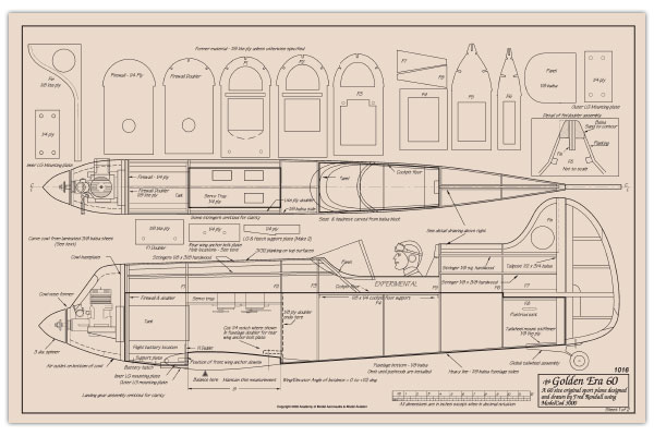
Type: RC sport Pilot skill level: Intermediate to expert Wingspan: 65.25 inches Flying weight: 10 pounds Wing area: 792 square inches Wing loading: 26-27 ounces/square foot Length: 51 inches Engine: GMS .61 glow Tank: Modeltech 360cc Flight battery: Four cells, 4.8 volts Radio: Spektrum DX7 system, AR7000 receiver, three DS821 and two Hitec HS-625MG servos Spinner: Du-Bro (LXE 149) 3 inch Construction: Balsa and light plywood Covering/finish: Builder’s choice (Sig AeroKote is recommended.)Order Plans from AMA Plans Service
Image
Image
Construction
I have always admired racing aircraft of the so-called “Golden Age of Aviation”: an era that extended from the end of World War I to the onset of World War II. It was the time of rakish designs, open cockpits, and “flying by the seat of one’s pants.” Aircraft designs of the time were largely grand experiments, and from those experiments emerged the Granville Brothers’ Gee Bee series, the Hughes H-1 racer, the Travel Air Mystery Ship, the Hall Bulldog, and the rest of the list, which is too numerous to include here. I was weary of going to our flying field and finding almost nothing between ARF training models, sticks, and the usual bunch of 3-D ARFs. I realized that if I wanted something with a style I liked, I’d have to build my own.Image
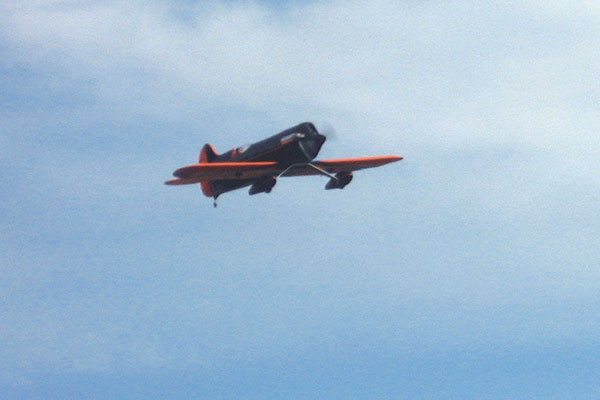
Grooving through the open sky, the Golden Era 60 handles as the popular Stick models do but has the looks of a 1930s racer.
Accordingly, I made a couple pencil sketches, loaded ModelCAD 3000 into my PC, and sat down at my electronic drawing board to play. The Golden Era 60 is the result. Although this airplane is conventional in its construction, it is unsuitable for a first scratch-building project. This article assumes that the builder has some experience beyond ARF assembly and is familiar with common building techniques. Unless you get the laser-cut “short kit” I’ll tell you about, you shouldn’t attempt this build without a scroll saw or band saw, a Dremel or other rotary tool, and the usual collection of hand tools. The judicious use of a square and straightedge is necessary throughout construction if you expect to manufacture a straight, easy-to-trim aircraft. If the previous paragraphs haven’t discouraged you, we can proceed. Materials: Creative Hobbies of Mendon, Massachusetts, sells a short kit of laser-cut 1/8 light plywood, 1/4 plywood, and 3/8 balsa parts at a reasonable cost. These accurate precut components and a full-size rolled plans set from MA will greatly simplify construction. It eliminates tedium, and what remains is the equivalent of building a good kit. Regardless of whether or not you purchase the short kit, I suggest that you have all fabricated parts (wing ribs, fuselage formers, etc.) on hand before starting the build. The landing gear and wheel pants on the original are Four-Star 120 parts ordered from Sig Manufacturing. I suggest that builders use the same parts since they are a good match appearancewise, they fit the gear mounting plates designed into the fuselage, and using other units may significantly change the balance point. But if you prefer to fabricate your own landing gear, have at it!
Image
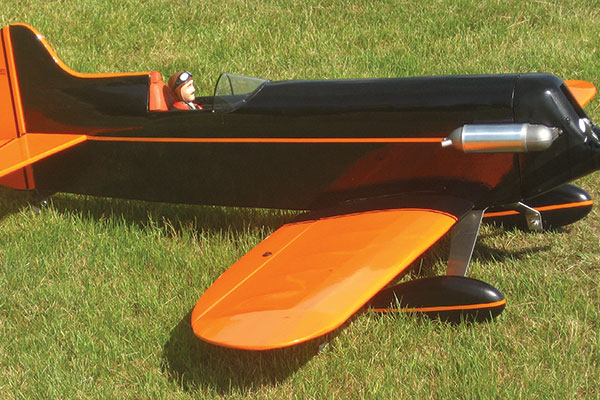
Stock Sig Four-Star 120 wheel pants complete this sport model’s 1930s racing look. The long and tall fuselage offers good knife-edge performance.
I did not design this airplane to be superlight since it is not intended for “3-D.” It has an allup weight of approximately 9 pounds and a wing loading of roughly 26 ounces per square foot. However, it is extremely strong. This model is extensively planked, including wing capstrips, and composite tubing is used for the LE and the main spar.
Construction
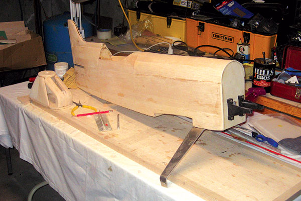
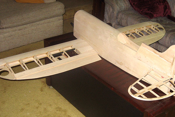
Fuselage: Although I usually begin with the wings, the fuselage was my starting point for this project. The first task was selecting the 1/8 balsa for the fuselage sides. The importance of matching the side sheets’ hardness and grain cannot be stressed enough. If the balsa is poorly matched, it will be next to impossible to make a straight fuselage. The fuselage sides’ maximum height is approximately 7 inches. I used matched 4-inch-wide, 1/8 balsa sheets. Cement them together with cyanoacrylate before cutting them to shape. (In the remainder of this document, cyanoacrylate means medium cyanoacrylate unless otherwise specified.) After you have cut the balsa sides to shape, use cyanoacrylate to glue the 1/8 plywood fuselage doublers in place. Be careful; it is easier than you can imagine to end up with two right or two left sides. Adhere, with cyanoacrylate, the doubler to the bottom of former F1. After the fuselage doublers have set, epoxy and clamp the two landing-gear (LG) and hatch-support rails to the fuselage doublers. Refer to the plans for position. Make sure to wipe off any excess epoxy from around the perimeter with alcohol. Epoxy the 1/8 plywood firewall doubler to the 1/4 plywood firewall. (Epoxy means 30-minute epoxy unless otherwise specified.) Lay the fuselage plans on your building board, protecting them with waxed paper or the like. With the plans as a guide, use a square referenced to the top of the fuselage sides to mark the position of all formers on the inside of both fuselage sides.Image
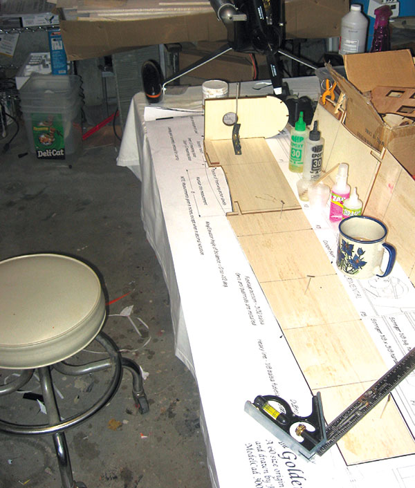
The former positions have been marked on the fuselage sides, and the firewall assembly has been epoxied in place.
Put the right fuselage side in place on the plans and secure it. Using a square to position it, epoxy the firewall/doubler assembly flush with the front of the fuselage side. When it has set, Formers F1 and F2 can be cemented in place using cyanoacrylate. Position the servo tray in the slots provided in formers F1 and F2, and secure it with cyanoacrylate.
Image

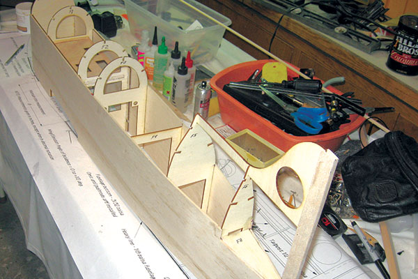
Formers F1 and F2 have been put in place, and the servo plate has been mounted between them.
Fashion the 11/2 x 47/16-inch rear wing anchor plate from 1/4 plywood. Do not drill it. Temporarily insert it into the slot provided in the fuselage doubler. Test-fit the left side for perfect alignment. The firewall assembly, the formers, the wing anchor plate, and both fuselage sides must align properly.
Image
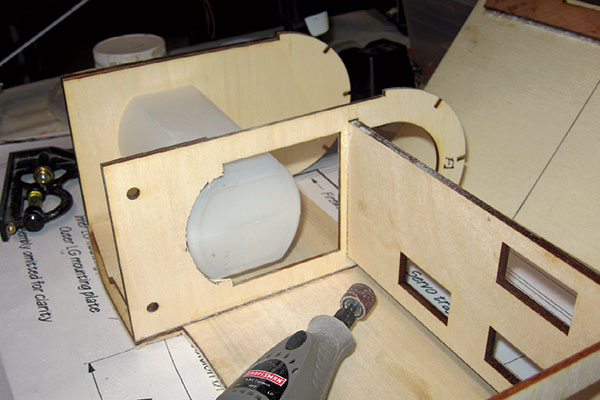
With the fuselage wide open, it’s a good time to fit the fuel tank. Silicone sealant will be used to mount the tank permanently.
When you are satisfied, remove the left side and apply epoxy to the edge of the firewall assembly and the wing anchor plate edges that mate with F2 and the fuselage sides. Apply cyanoacrylate to the mating edges of F1 and F2. Put the left side back in position. Place a book or similar weight on top to ensure a good bond, and then take a break.
Image

The left side has been epoxied in place after a careful alignment check. Notice how the rear wing mount is locked into cutouts in the doubler.
Shape the tail post from 1/2 x 3/4 x 13-inch balsa. It should taper from 1/2 inch at the LE to 3/16 inch at the TE. It is important that this piece be symmetrical. It will be further shaped and cut for the stabilizer later, during fuselage assembly. Notch the front roughly 1/8 inch deep to accept the light-plywood fin. Refer to the plans for notch location. With the fuselage secured to the top view of the plans, use T-pins to temporarily hold the rear of the fuselage sides together, sandwiching the tail post into position. The tail post should be centered over the plans and flush with the bottom and back of the fuselage sides. Ensure that the tail post is vertical in both axes when referenced to the fuselage sides. Reposition the pins until these conditions are met. Temporarily tack the assembly together using a few drops of thin cyanoacrylate. Remove the T-pins and recheck alignment. When you are satisfied, flow in more thin cyanoacrylate for a permanent bond.
Image
Bevel the tail post and then glue it in place. Dry-fit the fin and the remaining formers to assure good alignment.
Install the remaining formers using cyanoacrylate. If necessary, use rubber bands around the fuselage to ensure a full-contact fit. Employing the plywood fin as a pattern, make doublers approximately 3/8 inch wide from 3/16 balsa sheet. The doublers enable a smooth transition between the planking and the fin. There is a detailed drawing on the fuselage plans. Cement the balsa doublers to both sides of the fin with cyanoacrylate. Cut 1/8-inch gaps in the doubler where the fin fits into the F5 and F6 notches and another at the rear of the fin where it will be inserted into the tail-post notch. Install the fin and secure it with cyanoacrylate, and then sand the top of the tail post to blend with the fin and doublers.
Image
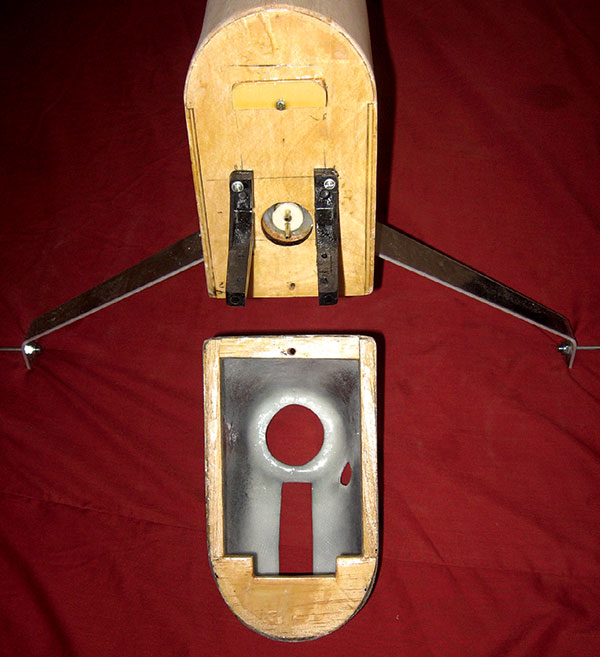
The tail-wheel mount area is supported by a 1/8 plywood plate. It’s recessed to allow room for balsa, which will be sanded flush with the fuselage sides.
Cut the cockpit floor from 1/8 balsa sheet. See the fuselage top view for the pattern. Using cyanoacrylate, install the floor as indicated and test-fit the dash panel. The dash panel pattern is somewhat oversize; you must sand it to mount flush with the cockpit floor and F3. Use a long sanding block to blend the panel with the fuselage. Install former F8. Fit it between F6 and the tail post. See the plans for location. Trim it as necessary for a proper fit. Ensure that F8 is at right angles to, and level with, the top of the notch in the fuselage sides. Take your time; this establishes proper alignment and angle of incidence. I found it helpful to cut a piece of 3/8 balsa sheet 3 inches wide and 12-15 inches long to use as a spacer and alignment aid. Lay it on top of F8 to use as a temporary substitute for the stabilizer.
Image
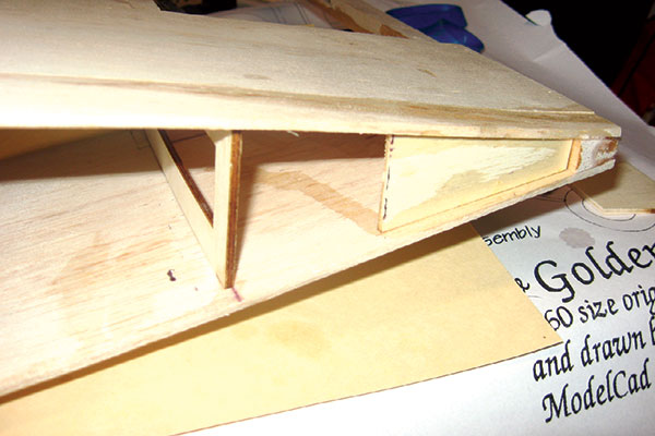
Scrap 3/8 balsa sheet is substituted for the stabilizer during preliminary alignment. The forward stringers are added at this point.
Position F7 as indicated on the plans, and snug it against the temporary spacer. Adhere F7 in place with cyanoacrylate and remove the spacer. Trim F7 as necessary for a proper fit. Install the stringers using cyanoacrylate. The front stringers extend aft to the panel. There are no notches in the panel, so shape the ends of the stringers for a nice butt fit against it. The rear stringers should terminate flush with the front of the tail post. Epoxy four 1/4-20 captive nuts to the inner LG mounting plate. Remove your fuselage assembly from the building board, flip it over, and use epoxy to bond the inner LG mounting plate to the support rails. Don’t spare the epoxy here; the LG takes considerable abuse (at least when I’m flying). The battery hatch came about because the finished model needed a bit of nose weight. I don’t like to add lead for balance when I can reposition something to compensate. I relocated the flight battery forward, in a foam nest made for perfect balance with no additional ballast. As a bonus, you have access to the LG support assembly, engine-mount captive nuts, and fuel tank should something go awry. Fashion the battery hatch from a piece of 1/8 light plywood. It should fit nicely between the firewall, the fuselage sides, and the LG mounting plate. It should rest on the support rails. Drill holes at four corners for your selected screw hardware. I band-sawed a small amount of downthrust and right thrust into my engine mounts before installation. Offset the mounts so that the spinner will be centered at the proper location. When positioned, drill the firewall and install the captive nuts. Empennage: Building this area is straightforward, and little explanation is necessary beyond what is on the plans. The only item that may need clarification is the elevator joiner. I originally intended to use a double pushrod for elevator control. However, I had a nice piece of .317 composite tubing left from the wing construction, and it seemed reasonable to use as a torque tube to join the elevator halves. If you prefer double pushrods, eliminate the torque tube and the clearance notch in the rudder. Wings: Select the right-wing full plans and secure them to your building board. Using cyanoacrylate, bond an RR1 rib to an RR2. RR1 should be inboard. This assembly forms the root rib. Bond an R3 to an R1. The rib with no LE notch is an R3; it should be inboard. Refer to the plans for confirmation. The wing will be built using the centermost bottom spar as a reference. Cut a piece of 1/8 x 1/4 basswood to length and secure it in place on the plans. Use a square to position the root rib assembly on the plans with the spar snug in its notch. Use cyanoacrylate to adhere the root rib assembly to the spar. Follow suit with an R1, R2 pair. Install the remaining ribs, and adhere them to the spar with cyanoacrylate. All ribs’ break-off stubs should lay flat on the plans. R2 is slightly different; it establishes a small amount of washout in the wingtips to improve low-speed stability. When all ribs are in place, cut and install the three top spars. Cut the .317-inch composite LE to length and glue it in place with cyanoacrylate. You should be able to insert the composite spar as far as shown on the plans. Test-fit it. It should be snug but not distort the ribs as it passes through. Make any adjustments needed until this condition is met, and then remove the spar. Remove the wing from the plans. Install the remaining bottom spars, and then check the assembly for straightness. It should lay flat, resting on the centermost bottom spar and rib break-off stubs. Correct any twist in the wing before proceeding. Following the diagram below the right wing assembly drawing, shape the TE from 1/2 x 3/8 balsa. When you are finished, glue it into position with cyanoacrylate.
Image
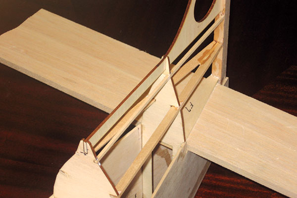
Notice the smart use of carbon-fiber tubing to form the LE and support the wing spar. The wing will be sheeted next.
Temporarily position the 1/8 light-plywood servo plate to the bottom of the wing. Make sure to place it at a point that is deep enough on the chord to ensure that a standard servo’s body does not protrude through the top. (Ask me why I added this instruction.) When you are satisfied with its position, adhere the servo plate in place with cyanoacrylate, flush with the bottom of the ribs. Use scrap 1/8 x 1/4 spar material to make rails to support and stiffen it. Use cyanoacrylate to glue the 1/8 lightplywood wingtip in place. It should be centered between the LE and TE and at right angles to R2. Make spar extensions and cement them between the rib and the tip. See the plans for positioning. Snap off the rib stubs and sand the areas smooth. Remove the right wing plans from the building board and replace them with the left. (We don’t want two right wings, do we?) Take a deep breath and repeat the wing instructions. Having completed the framing of both wings, fabricate and add the 1/4-inch plywood dowel support webbing and the wing mounting dowels. Ensure that the pegs will align with the holes in F1. The detail diagram will aid in drilling the peg holes and installing the pegs. Cut the .505 composite-tubing spar to length and test-fit the joined wings. Be sure to allow for the 1/16-inch planking. This work is critical; it affects the final wing leveling and wing/stabilizer angle of incidence. If the wing is too wide, it does no harm to remove some material from the TE where it fits within the fuselage. Wing Planking: The LE planking is a 1/16 x 12 x 36 balsa “wing skin.” The plans indicate the areas that are covered with planking. Do not trim the width until it is installed. Thoroughly soak the balsa with Windex and wait several minutes before attempting to make the sharp LE bend. When the balsa is pliable enough to make the bend, start at the top, rear 1/8 x 1/4 spar. Use cyanoacrylate to bond the balsa to the spar. Clamp it along its length until the adhesive sets. Work slowly. Starting at the middle of the wing and moving outward, glue, with cyanoacrylate, the ribs, front spar, LE, etc., until you have the entire wing skin bonded, top and bottom. If you do the job properly, the planking should be tight, with no bulges. Trim whatever planking extends beyond the center, bottom spar. Install the remaining planking and the rib capstrips. It’s better to plank the entire wingtip on both sides; it makes the covering job easier and neater. When you have finished both wings, prepare them to accept covering. Fuselage Planking: Starting with the front deck, plank the fuselage with 3/32 sheet balsa. I made a cardboard pattern and used it as a guide to cut the planking for the forward “hood,” from the firewall to F3. Soak the planking for installation. After test-fitting, use cyanoacrylate to install it. Make the 3/32 balsa planking for the area aft of the cockpit. Use a single piece to cover from F5 to the tail post and up to the 1/8-inch top stringer on each side. This piece should cover the tail post and terminate at the back of the fuselage. The bend is fairly gentle and should pose little problem. When you are satisfied with the fit, glue the planking in place with cyanoacrylate. Shape and add the pieces that go between the top stringer and the fin doublers. When the cyanoacrylate has set, use a sanding block to shape the back of the tail post so it is flat. Blend the planking into the fin doubler and the fuselage sides.
Image
Once the sheeting is complete, it’s a good time to test-fit the landing gear and engine mount. The cockpit area can be detailed at this time.
Cut two pieces of 3/8 balsa stock 11/4 inches wide and 83/8 inches long. These fit between F5 and the instrument panel. Shape the fronts to fit flush with the panel. Position them so they are 3/32 inch inboard of the fuselage sides, and adhere them in place with cyanoacrylate. Sand both sides so they follow the contour of the panel and F5. These provide support for the planking around the cockpit. See photos for clarification. Shape and fit the planking around the cockpit. When you are satisfied, sand everything flush. Use balsa filler to fill any gaps, and finish-sand the entire fuselage smooth and even. Cut—but do not install—the 3/32-inch bottom piece. With the fuselage planking complete, cut the tail post for the stabilizer. This marks the end of the planking phase. Ailerons: These are cut from 3/8 x 3 tapered balsa. See the wing plans for patterns. Before shaping the aileron LE, use cyanoacrylate to laminate a matching piece of 1/16 hard balsa to the top to strengthen the structure. Temporarily attach the ailerons to the wing with a few small spots of cyanoacrylate, and then block-sand the bottom of the ailerons to blend with the wing TE. Remove the ailerons using debonder, and sand the LEs for hinging. Pushrods, Etc.: Install the pushrod tubes. Holes are provided in F4 to support the front of the pushrod tubes. I crossed mine in the middle and they exited the fuselage on the opposite side. I used a small cable tie at the crossover point to support and stiffen the tubes. Once the pushrod tubes are installed, use cyanoacrylate to glue the bottom piece in place. Sand the joint smooth. A 360cc tank (Global Hobby part 120074) I had on hand was employed in the original. I used silicone adhesive to bond the front of the fuel tank to the inside of the firewall, with the neck protruding through the provided hole. I Dremeled the bottom of the hole in F1 to match the contour of the rear of the tank (see dotted line on F1 pattern) and used silicon adhesive there too. Drill a hole in the firewall and F1 for the throttle pushrod, positioned to make a straight run from the carburetor to the throttle servo. The fuselage servo linkages are typical. Use your favorite clevises, etc. The wing servos and linkages are installed after covering. There are large openings in the ribs that provide passage for the wires from the servos. Make small openings in the planking inboard, on the top of the wing, for the servo wires to exit. Insert the .505 composite wing spar in one (either) wing up to the rib just past the servo and glue it in place inside the root rib (only) with cyanoacrylate. It is unnecessary to cement the wing halves together. It is much easier to store and transport them separately. The mounting pegs and nylon bolts will align and secure the wings to the fuselage, and the spar is more than strong enough to prevent them from folding. Cowl: For the original model I made my cowl from laminations of 3/8 balsa. Several good articles have been written about the subject. I also made a balsa cowl for a second airplane, and I sent it out for Fiberglass Specialties to duplicate in fiberglass. These cowls are available for purchase if you don’t want to expend the effort to fabricate your own. Either way, the weight difference is slight so the balance remains unchanged.
Image
Build the cowl from wood or purchase the fiberglass version from Fiberglass Specialties. The mounting screws are hidden inside.
Covering: It seems like everyone has a favorite covering material; I am no different. I prefer Sig AeroKote, which I used on the entire aircraft. I don’t care for the elaborate, multicolor schemes festooned with sponsor logos that are rampant on ARFs. Thus Brodak’s CL Oriental was the inspiration for the color scheme I used on the original Golden Era 60. The Oriental is black and red; I opted for Black and Naval Orange. If you use black on the fuselage, throw a white cloth over it if the model is going to sit in the sun for a long period. The black covering absorbs heat and loosens, and you will be faced with a session with the iron and heat gun when you get home. Nuts and Bolts: I used Du-Bro heavy-duty .40-.91 control horns (item 867) throughout. They require a single hole for mounting and are rugged and easy to install. A bonus is that they adjust for angle as well as throw. I installed a steerable tail-wheel assembly from Global Hobby. It mounts easily and works well. My Spektrum DX7 came with four JR servos. Three are used in the fuselage, and Hitec HD servos are used for the ailerons. The Spektrum dual receivers are mounted on opposite fuselage sides using Velcro. They are oriented to provide opposite antenna polarity, as the installation instructions mandate. Not having to provide routing and an exit for a long 72 MHz antenna is a pleasant change! The double 1/4-inch plate used to mount the LG is a work-around because of a clearance issue. The wing extends forward from the mounting recess and engages the LG if additional clearance isn’t provided. I didn’t realize this until too late, and the second plate proved to be a quick, effective remedy. I cut the windshield from a plastic cake container my supermarket provided free of charge. Ask for one. If they refuse, you can buy a cake and eat it!
Image
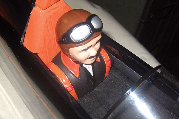
A Williams Brothers Sportsman pilot bust complements the open cockpit. Enamel brush paint can be spray-fixed with a fuelproof clear coat.
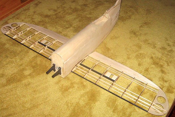
The seat and headrest are carved from balsa block and brushed with one coat of Insignia Orange Aero Gloss. It imparts an almost suedelike appearance. “Leo,” the pilot, had to have his shoulders trimmed to fit in the narrow cockpit. I repainted him with my wife’s acrylics to match the model. (References to “Leo” stem from the pilot figure’s uncanny resemblance to a friend and fellow RCer, Leo Desmarais.) Hinging: I used cyanoacrylate hinges throughout, but regardless of the type you should have at least two on each elevator half, three on the rudder, and four—equidistant—along each aileron. Mounting procedures vary, depending on the type chosen, and hinge installation instruction is beyond the scope of this article. No matter what type of hinge you use, make sure the movable surfaces fit closely to the fixed surfaces. Gaps give birth to control flutter, which can end an otherwise perfect flying day. Assembly: Since this is probably not your first scratch build, I’ll be brief. There is nothing unusual about the model and assembly is straightforward. Assuming that the covering job is finished and the elevator is hinged, insert the stabilizer into its slot. Make sure it’s straight using a string from the nose to the elevator tips. Mark the stabilizer where it joins the fuselage, top and bottom. Remove the stabilizer and then remove the covering that will be within the slot. Permanently adhere the stabilizer, with cyanoacrylate or epoxy, and hook up the control hardware. Drill the LG to accept the 1/4-20 nylon mounting bolts. If the wheel pants haven’t been assembled and painted and the wheels haven’t been mounted, you haven’t been reading far enough ahead! Assemble the wings and fit them to the fuselage. With the wings seated, carefully drill 9/32-inch holes through the centers of the wing reinforcement pads into the rear wing mounting plate.
Image
The completed one-piece wing is mounted with dowel pins and nylon bolts. The light tail structure is designed to keep the weight mass balanced on the recommended CG.
Remove the wing and then further drill the mounting plate to accept the captive 1/4-20 nuts. Epoxy them in place on the backside. When they are set, reinstall the wing and insert the 1/4-20 nylon bolts. Screw them into the mounting plate slightly more than finger tight. Check the wing-to-stabilizer angle of incidence using your favorite method; I use a Great Planes laser setup. If your build is accurate, it should be 0°-.5°. If it isn’t, make it so. You can correct it several degrees either way by removing or adding material to the rear part of the wing saddle. Balancing and Flying: I suggest a slightly nose-heavy configuration for the first flights. The balance point should fall one-third back from the LE, or approximately where the LE planking ends. Being an RC novice, I have left the balance point there. If you’re more experienced, you may find that a slightly more aft point allows for better aerobatics. This airplane has a thin symmetrical wing, a somewhat short tail-moment arm, and high wing loading; therefore, it flies like a warbird—fast and without self-righting properties. I programmed flaperons to help during landings. Keep power on during approach. As does a warbird, the Golden Era likes to come in under power. The large control surfaces beg dual rate and exponential programming. This will allow the experienced pilot to burn holes in the sky while the less confident can fly it around without working up a sweat. The deep fuselage makes for easy knife edge, and the slight wingtip washout and aileron configuration help to keep it from falling out of the sky at relatively low speeds. This is not a good design for a first low-wing sport airplane. It is satisfying for the intermediate pilot and will draw attention at the club field.
Image
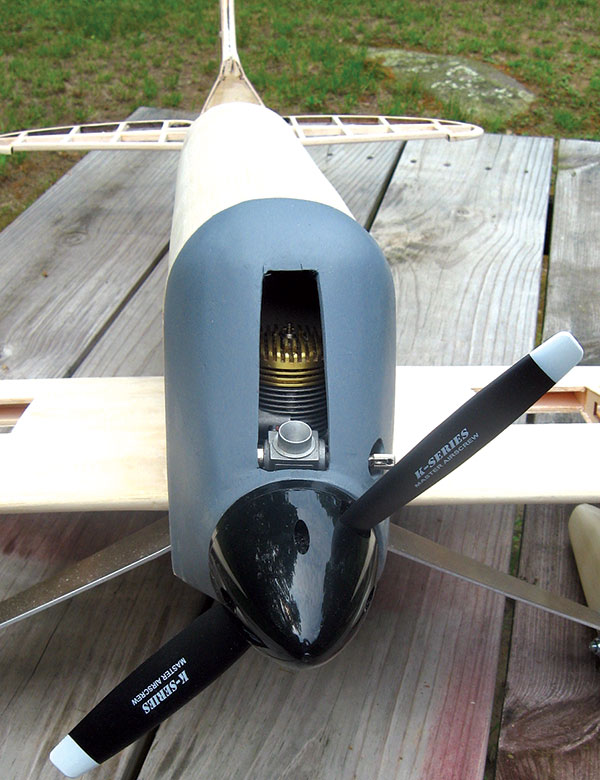
The GMS .61 two-stroke engine hides inside the spacious cowl. A four-stroke .82-1.00 would also fit this model neatly.
Electric Dreams: I gave little consideration to making this aircraft light beyond what was necessary for good 60-power performance. It came in at slightly more than 9 pounds dry. An electric conversion could include fewer doublers, thinner and less planking, more lightening holes, and a lighter LG assembly. Several pounds could probably be shaved off easily, making the wing loading nearer to a more acceptable 20 ounces per square foot. Being an old FF Gas aficionado, I revel in the smell of nitro fuel in the morning, and the postflight cleanup is akin to a labor of love. I’ll leave it to you wattage mavens to do the converting, but I’d love to see the results! -Fred Randall


Comments
Nice workmanship - But a 4Cell NiMh?
Beautifully executed project. Nice write up too! However, Spektrum specifically addresses not using a 4 cell NiMh on AR Rxers. They specifically call for at least a 5 cell. With all the load on the circuits, a 4 cell quickly can reach 3.5 volts and the Rxer goes dead, even on a momentary voltage drop. Check out the AR 7000's manual. I certainly would not risk a 4 cell on such a beautifully crafted plane.
New Era plane
Great article . Any thoughts on the biplane version? I bought the planes and read an earlier story about the plane, but the upper wing mounting used was just plain ugly. Love the design though.
Thanks Clark
Cowl Covering
if the fiberglass cowl is used, what is being used to color it that will withstand glow fuel. It's becoming quite the conundrum for me and I've basically resorted to balsa cowls so I can cover them :(
Kit?
Is there anywhere to get this as a kit? Thanks.
Add new comment