
Build the SkySpringer Keep it simple with this fun project
by Clark Salisbury ([email protected]) | Photos by the author
As seen in the October 2019 issue of Model Aviation
Download free plans!
Image
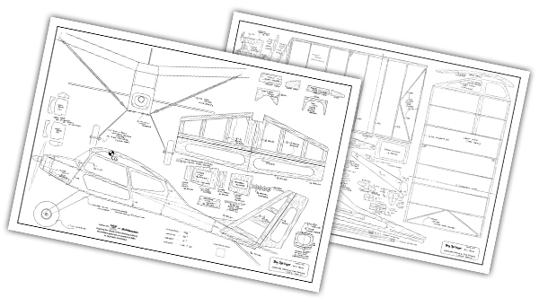
Full-size plans
Tiled plans
Order Plans from AMA Plans Service
Image
Image
Download bill of materials!
Document
At A Glance
Specifications Wingspan:40-1/2 inches Height:14 inches Length: 32 inches Motor: E-flite Park 370 1,080 Kv brushless outrunner Battery: Three-cell 11.1-volt 1,300 mAh LiPo Weight: 1 pound, 7 ounces Before you build this little airplane, I need to explain why I dreamed of it in the first place. In 2000, I designed an airplane called the SkyCrawler. I have since designed quite a few other airplanes, but the SkyCrawler is one of the slowest and most forgiving designs that I have done. Because of its undercambered high-lift, high-drag wing, the airplane flies slowly, which is excellent for anyone who is learning to fly. The other characteristic of this design is the Short Takeoff & Landing (STOL) distance. Because of its big wheels, the aircraft can also be flown from grass at any park or soccer field. The SkySpringer is simply a more modern-looking version of the SkyCrawler, using the same wing but with an enclosed fuselage. In this design, weight and size were critical because I wanted to be able to transport this airplane in the back of my Lincoln Mark VIII car or a trunk without detaching the strut-supported wing. This airplane is a three-channel design instead of a four-channel with ailerons because the high-dihedral wing effectively banks well when rudder is applied. Just think of the rudder as “sliding” the airplane left or right, forcing the wing to bite into that air on either side and causing it to bank. The SkySpringer is designed as a beginner, non-aerobatic airplane and it excels in that role. I recently began adding LED lights to my models, including cars, trucks, boats, and aircraft. Using two AAA rechargeable batteries to power the LEDs, I can now operate many models in the dark. The SkySpringer, which “springs” into the sky, can be flown at night, although I recommend flying at dusk to get used to the lights before flying in total darkness. Let’s build! Cutting Out the Parts All of the parts that need to be cut out are on the plans—mostly on page 2. The horizontal stabilizer and vertical stabilizer pieces are only shown in one place and they need to be cut out carefully from where they are. The wingtips are also only shown in one place and will have to be cut out from there. When building the fuselage sides, glue the plywood pieces together so that both sides can be cut out at the same time with a scroll saw. In Figure 1, you will see how the drawing cutouts need to be added to the balsa block to cut out the wingtips. Make sure you build a right and a left wingtip. You will need to cut the 2 x 3 x 12 block in half to be able to make two wingtips.Image

Figure 1.
When cutting out the wing ribs as shown in Figure 2, the 1/8-inch balsa can be stacked and glued together. Do not add glue except on the outside edges so that you don’t glue the ribs together.Image

Figure 2.
Tail Feathers In Figure 3, the horizontal stabilizer is shown glued together and pinned to a corkboard (or use a piece of drywall). I found it easier to slot the 1/8 balsa pieces for hinges before gluing everything together. I used a small, thin cutting wheel on my Dremel tool to start the slots then finished them with a sharp X-Acto knife. Test-fit the nylon hinges into the slots to ensure that they fit.Image

Figure 3.
Wing In Figure 4, wing construction has started. I laid out the left and right wing patterns side by side on my table. First, glue down the leading edge (LE) dowel then glue the front of ribs R2 and R3 to the LE dowel. The R1 ribs will be glued in later. This is noted on the construction photo (Figure 4). And yes, I changed my design as I was building.Image

Figure 4.
Pin the rear of every rib to the table then lay the trailing edge (TE) dowel in position and glue it at the top where it will meet the rib. Then simply rotate it into position and pin it to the rear of all of the ribs. In Figure 5, the wedges are glued and pinned to the inside of the ribs and to the LE and TE dowels. Make sure you put the bottom line of the wedge on the table. Note that it takes two wedges in each place for a total of eight. These wedges will later be used to support the wing strut mounts.Image

Figure 5.
In Figure 6, the wingtip is glued and pinned in place along with the 1/2 x 7-inch piece of balsa, which connects the wingtip to the top of the outer ribs.Image

Figure 6.
In Figure 7, the wing halves have been joined. Line up the left wing half and the right wing half perfectly with a 2-3/4-inch gap between them. Cut two pieces of 1/4-inch dowel to 2-3/4-inches long and sand off the ends to a 10° angle. These will be the LE and TE joiners.Image

Figure 7.
Join the wing halves using the plywood dihedral joiners. Lay VHS tapes on the dihedral joiner lines on both sides or just measure 5-3/4 inch from the inside edge of where F1 will be. If you don’t have any old VHS tapes, use anything that is exactly 1 inch thick. Pin and clamp that together and let it dry. Glue in R1 on both sides and the three balsa wing joiners that will connect R1 left to R1 right. When that has dried, glue in R4 and R5, the diagonal ribs, on both sides. Let that dry then remove the wing from the board and glue in the wing strut mounts on top of the balsa wedges that were placed in the previous step. When that is dry, the entire wing can be sanded as needed to make the wingtips match the wing ribs, etc. Fuselage Figure 8 shows a subassembly being built. The landing gear mount is what four of the LEDs will be mounted to. Glue in four balsa wedges to the top side of the landing gear mount. When these are dry, glue the two wing lighting LED mounts to the top of the wedges. These are two of the long mounts. When that has dried, glue in the two short LED mounts to the bottom side of the landing gear mount. Note that you will need to draw in pencil where these items are located on the mount.Image

Figure 8.
Another subassembly is being built in Figure 9. This is the 1/16-inch plywood piece with the gauges on it. Note on the plans that some grooves need to be carved out between the gauges where the leads to the yellow LED can be placed. The long lead wire on all of the LEDs is the positive side. The LEDs will only work if the positive side of all of them goes to the positive terminal of the batteries.Image

Figure 9.
With the gauges glued in place, the instrument panel can now be glued to the top of the subassembly that was just built. Secure it with clothespins until it dries. All of the wood pieces should be painted with the interior color before mounting anything to them. I used a dark gray. In Figure 10, the LED lights have been installed and are powered on. To accomplish this, start at the left side of the photo. The plywood battery tray was glued to the bottom of the instrument panel. Note that the two holes in the battery tray are for the red and black wires to go through. The plastic battery holder is also screwed to the plywood battery tray with two small wood screws.Image

Figure 10.
The landing gear mount piece is pinned in place 3 inches to the right of the instrument panel. All four LEDs were first epoxied in place in the bottom of the landing gear mount and on both sides at an angle for the LEDs that will illuminate the wing through the bottom window. When the epoxy dries, the leads on all of the LEDs can be bent to where they touch each other. This makes soldering the positive and negative wires much easier (just make sure to keep track of the positive and negative wires). Former F6 is pinned to the board 5 inches to the right of the landing gear mount. Note that the LED mounts were already glued to F6 and that they protrude 9/16 inch above the top of F6. The wires are soldered to where the last two LED leads cross each other. This completes the LED installation, which you can test with two AAA batteries. Figure 11 shows that fuselage formers F3, F4, F5, and F6 have been glued to the fuselage’s left side panel. Getting the prewired LEDs through all of this is tricky, but possible. Note that all of the formers and the side panels are prepainted. Don’t paint where glue will be applied.Image

Figure 11.
Note that the landing gear mount has been glued to the fuselage side panel. Use something square to ensure that it stands perpendicular as the glue dries. Instrument panel F2 is just loose at this point. After this has dried, glue on the right fuselage side panel. This is also a good time to glue in the instrument panel. Although not shown in Figure 11, the two 1/16 plywood pieces that are 3/16 x 1 inch should be glued up against F3 where the windshield screws will later be installed. The plans show these pieces on the side view of the airplane. Figure 12 shows front former F1 glued in place, as well as the rear window and F7. All of these parts are held in place with masking tape around the fuselage.Image

Figure 12.
In Figure 13, the upper front and rear cowling pieces are glued in place. The rear cowling piece is actually two pieces. The inner piece is the access door for the AAA batteries that power the LEDs. Small tabs will need to be glued onto that piece to hold it in position, and a small scrap piece must be glued in between F1 and the battery holder. This piece needs to have a #6-32-size hole drilled and tapped into it so that a small #6-32 screw can hold the cover in place.Image

Figure 13.
On the front, glue two nose cowling mounts in the bottom corner of each side of the front of F1. These will also need to be drilled and tapped to a #6-32-size thread so that the nose cowling can be held in place with a couple of #6-32 screws. At the rear of the fuselage, the top piece can be glued in place, but before doing so, epoxy in the rudder and elevator servos on the underside, as shown in Figure 14.Image

Figure 14.
Figure 15 shows the electronics, battery, and motor installed in the fuselage. This needs to be done before the bottom fuselage pieces are glued in place. When the motor is screwed onto F1 using the supplied screws, make sure you grind off the part of each screw that protrudes through the back of F1. Otherwise, the LiPo battery will rub against the sharp screws.Image

Figure 15.
The pine nose piece is not shown, but it was attached and sanded to its final shape at the same time that the front of the fuselage was sanded, so that the radius would match the top of the instrument panel. The nose piece must be painted because of its complex curvature. Also paint the lower strut mounts with the 35° gussets glued to them. These pieces are too complex to cover. Paint both sides of the aluminum landing gear pieces yellow. You can see in Figure 16 that the bottom fuselage pieces have been glued in place with pins. It is not shown, but before the front bottom fuselage piece is glued in place, the battery retainer studs must be glued to the rear of F1 and the front of F3. These should be glued with the notch forward on F1 and the notch rearward on F3 so that an elastic can later be attached to these studs to keep the battery from falling out. The wooden studs should protrude through the lower fuselage approximately 3/16 inch.Image

Figure 16.
Note that the charging leads and battery connection to the ESC poke out through the hole in the bottom of the front cowling. Make sure that these electrical connectors cannot come forward enough to get close to the propeller. The motor should also be securely fastened to F1 with the supplied screws. This is an excellent time to ensure that all of your electronics work and that your propeller spins the right way. Have somebody hold the fuselage when you test this. If you plan to run up the rpm on the propeller, make sure you tighten it first. This seems obvious, but oops ... I learned the hard way and the propeller spun off. Figure 17 shows finishing the bottom of the fuselage. Cut approximately 18 inches of the 1/8 x 1/2-inch balsa strip in half. Fill in the remaining gaps in the fuselage bottom outside edges with these pieces between F4 and F6, etc. When that has dried, sand a nice radius along the corners of the fuselage, both top and bottom.Image

Figure 17.
In Figure 18, the wing is located on top of the cabin. Holes are drilled through the wing and into the four wing mounts on top of the fuselage. After drilling and tapping the first hole, a #6-32 nylon screw can be inserted to hold the wing in position while you finish the remaining three holes. Yes, that is a garbage can in the photo. It holds the fuselage nicely because there are already LEDs sticking out of the bottom of the fuselage, so it can’t sit flat.Image

Figure 18.
Remove the wing, turn the fuselage upside down, and tap the #6-32-size holes in the bottom of the fuselage for the landing gear. The landing gear can be attached with four screws then a drop of epoxy is placed on top of each screw to ensure it doesn’t come loose. Hold off on the epoxy because the landing gear will need to be removed when you do the covering. Note in Figure 18 that the fuselage-mounted strut mounts have been painted and glued to the bottom of the fuselage. They should be even in front with the landing gear mount piece. An optional step is pictured in Figure 19. My plans include a pattern for seats. I made mine from a piece of foam packing from something else that I had bought. My seats were so lightweight that they did not register on my scales. I used toothpicks for the seat supports. They stick out 7/8 inch and at an angle so that they can be glued to the bottom of the cabin.Image

Figure 19.
The pilot was purchased at Walmart and is a Funville Sparkle Girlz doll. With the lower body removed and a significant haircut, she only weighs 5/8 ounce. She might be a ground pilot for display after I do my flight testing. Figure 20 shows all of the struts cut out of 1/8-inch plywood. Each strut has two 1-inch long threaded #2-56 rods epoxied into the slots at both ends. Use a small piece of masking tape over the protruding rods and paint all of the struts yellow.Image

Figure 20.
Covering Figure 21 shows the parts individually covered with UltraCote ParkLite bright yellow. This covering is lightweight and thin but is not opaque. Make sure you either sand off or erase any markings on the wood you will be covering. When I covered the wing, I attached the covering around all edges and ribs then pinned the wing down from the outside to my drywall board before doing the final shrink between the ribs.Image

Figure 21.
Let the wing cool before removing the pins around it. This prevents the wing from bowing. If you don’t do this, the wing will bow significantly. Do not put any covering on the bottom of the wing—only the top. That gives the wing extra lift and drag and will make for short takeoffs and landings. Several parts should be painted before covering, including the aluminum landing gear and the front nose piece. Because the covering material is semi-transparent, it is good to have a base coat of yellow paint first (I used Krylon Fusion gloss sunbeam color from The Home Depot). The UltraCote covering shrinks so well around corners that you will be able to cover the parts to achieve the right color. Final Assembly In Figure 22, you can see that the servos have been hooked up to the elevator and the rudder using Du-Bro nylon control horns. I found it easiest to bend the control rods first. I bent each end of the .039 steel music wire rods then inserted the bent ends into the servo arm and the control horns. I then gently pushed the control horn barbs into the elevator and rudder.Image


Comments
Looks like a fun build and
Looks like a fun build and hopefully easy to fly for an "R/C challenged" person such as myself.
Skyspringer
Looks like a great design. I'm an older "back at it again after many years" rc flyer. The reflexes and vision are not what they used to be and a slow STOL 3 Channel airplane is very attractive to me. I think this one will be next on my build list. Thanks for a great new plan!
Gas?
Would this bad adaptable to an .061 glow motor with throttle control?
Looks like a fun airplane to
Looks like a fun airplane to build and fly i think ill try it
Gas?
Can this handle an .049 gas engine?
Sky Springer on a glow .049
I doubt it would be suitable unless you are going to dope the plane to protect it from the fuel's oil, methanol, and nitromethane. Fuel tends to be hard on covering seams and with only the top of the wong covered...
The interior would need sealed off from the fuel spray in the cockpit area and any internal areas accessed from hatches as well.
So, yes you could fly it slowly with a 1/2 A but it is going to be a lot more work to build it.
Unless it is throttled 1/2A motor it will be a different flying experience and you will have to be happy with the motor output at whatever speed it settles into. But years ago the QTee and STee and other planes were flown with 1/2A motors and this is not terribly different size from those relatively slow fliers.
plans
I ordered a set of plans and when I received them I find 2 sheets of the number 2 sheet. Could you send me a rolled plan number 1
thank you
Plans problem
Substitute Motor
It appears that the Park 370 is no longer made, what would be a good substitute?
I’m building this now
Thanks for this plan. This is my first from scratch balsa build. I’m doing it in Australia and have had to make a few substitutions but it’s going well and I’m really enjoying it.
My buildlog for the SkySpringer is up at RC Groups
As I build the SkySpringer I am keeping a buildlog at RCGroups.com You can find it here https://www.rcgroups.com/forums/showthread.php?3545273-SkySpringer-by-C…
So far so good!
Finished Building
I just completed building this little model. It's lots of fun putting around super slow. We had a successful maiden flight, it springs up into the air for sure. It actually tries to go straight up if I give it full throttle. I have it overpowered, but may suggest pointing the motor down slightly to counter this effect. The SkySpringer didn't survive our first training session though. The plywood wing joiners and struts were not enough to withstand pulling out of a dive. I'm reinforcing my wing now with aluminum wing joiners. I also plan to replace the side-mounted strut links with an aluminum strut link sandwiched between the landing gear and fuselage. This will ensure strength in the strut structure. I may also want to use the dowel struts (instead of the plywood struts), and will want to reinforce the strut links to the wing with epoxy at least. Fun aircraft, and a good trainer as far as stability goes. Certainly a good scratch-build to start with. I got mine done in 6 weeks.
Add new comment