
Written by Louis Joyner
FREE FLIGHT DURATION
As seen in the May 2015 issue of Model Aviation.
For any rubber-powered model, the propeller is one of the most important components. For maximum duration, it is vital that the propeller be carefully matched to the rubber motor and that both are suited to the model and to the way it needs to be flown.
For example, the motor and/or the propeller can be altered to increase motor run for calm air flying, or to shorten the motor run to speed up the climb to get through ground turbulence in windy conditions. Reducing motor cross-section (e.g., using fewer strands) or increasing propeller pitch will increase motor run, while increasing motor cross section or decreasing pitch will shorten motor run and give a faster initial climb.
For some events such as P-30, propeller choices are slightly limited, but even between the commercially made plastic propellers there are some variations in propeller pitch. For many other rubber events, the pitch, as well as diameter, blade width, and blade shape are unregulated. This allows wide latitude in propeller design.
Because pitch is the easiest propeller parameter to change in the field, models often feature hubs with fittings that allow propeller pitch to be adjusted on the ground. This is not the same as the variable-pitch hubs frequently used on F1B and F1G models to change pitch during the motor run, decreasing pitch as the torque drops off.
What exactly is pitch? It is the theoretical distance that a propeller blade would move forward in one revolution. Pitch is typically measured at 67% to 75% of the propeller radius. Knowing the blade angle and the circumference, you can draw the pitch graphically, or use a scientific calculator to quickly determine the pitch.
The formula is P=TanA • 2r r. (P is pitch; TanA is the tangent of the blade angle; and r is the local radius.) For example, a 600mm diameter propeller with a blade angle of 30° at 0.7 radius: P= 0.57735 x 2 x 3.1416 x 210mm = 761.80mm.
It only takes a slight difference in blade angle to make a significant difference in pitch. In the previous example, an increase of 1° in blade angle increases pitch 31.02mm, or about 1 3/16 inch or slightly more than 4%. So it is important that both blades be accurately set to the desired angle. For this, most rubber fliers use some sort of gauge to measure blade angle, typically at a set point out from the hub. This requires either an adjustable angle finder or a set of angled gauges.
A third method utilizes a fixed angle, such as 30°, that is moved in or out from the hub to change the radius. This works with helical pitch propellers, but not with most modern propeller designs that have a different pitch at each radial station. For example, the pitch might be lower near the hub, increasing to a maximum at 70% radius, then decreasing toward the tip.
To measure and set blade angles, I made a jig with a range of angle gauges that can be easily swapped out. To me, this method offers better repeatability than does a system using an adjustable angle with a degree scale. My blade-angle jig consists of a small box made from1/8-inch birch plywood, a turned aluminum fitting to hold the propeller hub, and a series of angle gauges also made from 1/8-inch plywood. The angle gauges store inside the box, along with a small wrench and an extra aluminum fitting for use with a different propeller hub.
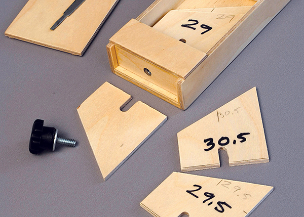
The box I made for F1B propellers measures 9 inches long, 2.25 inches wide, and 1 inch deep, but dimensions are not critical. What is critical is the distance from the center of the hub-holding fitting to the end of the box. This determines the radius used to determine blade pitch. In this case I used 200mm, which is a fairly standard radius station for setting F1B propellers. (Actually, the distance I used is 198.5mm to allow for half the thickness of the 1/8-inch plywood gauges.)
At one end, the sides and bottom of the box extend 1/8 inch past the top, creating a recess with a ledge to accurately locate the angle gauges. Pieces of1/32 x 1/8-inch basswood were glued on the inner face of the side extensions to slightly reduce the width of the recess so the angle gauges would fit inside the box for storage. A blind mounting nut in the end of the box and a plastic-knobbed screw hold the angle gauge in place.
The angle gauges were made after assembling the box so I could make sure the gauges would perfectly fit the recess. I made 1-foot strips of 1/8 plywood then cut a different angle on each end using a chop saw. The saw’s angle settings were surprisingly accurate, but I checked each one with a digital protractor, making slight adjustments as needed with a sanding block.
The angle gauges were then crosscut to length. The length was determined by measuring the distance from the centerline of the rear face of the propeller blade to the top of the recess ledge. This distance does not change with blade angle changes.
Each angle gauge is the same height at the center of the angled side. I made five angle gauges in 0.5° increments to cover 29° to 31° for setting blade angles on my fixed-pitch front ends. For variable-pitch front ends, I used 24°, 24.5°, 25°, and 26°. (With variable-pitch front ends, blade angle is set at low pitch. Under high torque at launch, the blade angle increases approximately 11°.) Each angle gauge is notched at the bottom to fit around the screw in the end of the box.
The box lid is a piece of 1/8-inch plywood with 1/16 x 1/8-inch basswood strips glued to the underside to locate it. Instead of hinges and a latch, I simply used two rubber bands to hold the lid in place. The rubber bands do double duty holding hub and blade while adjusting the blade angle.
To accommodate the smaller-radius F1G propellers, I made a piece of plywood that fits over the F1B hub fitting and has a second hub fitting for F1G hubs located closer to the angle gauges (150mm vs. 200mm). This allows the same set of angle gauges to be used for both F1B and F1G propellers.
If you don’t have access to a metal lathe, fittings to hold propeller hubs could be made from plastic plumbing connectors or from plywood blocks drilled to fit. For models with square or rectangular nose blocks, you could make a series of interchangeable plywood fittings.
As an alternative to making a plywood box, look for ready-made wood boxes at craft stores. Or you could use a piece of wood, such as a 1 x 3-inch pine strip for the base, and store the angle gauges in a plastic bag.
Image
The bottom and sides of the box extended out to locate angle gauges. A plastic-knobbed screw holds the plywood angle gauges in place.
SOURCES:
National Free Flight Society (NFFS) www.freeflight.org
Image
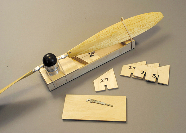
Accurately setting the propeller pitch requires an angle gauge. This homemade unit utilizes interchangeable angle gauges and a turned aluminum fitting to hold the propeller hub. An assortment of gauges is stored in the plywood box.
Image

For smaller models, a 1/4-inch plywood plate holds the propeller hub closer to the angle gauge. Typically, the distance from hub center to angle gauge is approximately two-thirds of the propeller radius.


Comments
I like this article.
I like this article.
DC-3 typical pitch for Guil balsa model prop.
I’m about to build the two props for my model and wondering what pitch angle would fork best for spinning with a fan blowing on this otherwise static model.
Add new comment