Written by Stan Burak
How to determine your CG
As seen in the February 2014 issue of Model Aviation.
Dealing with our aircraft’s center of gravity on our RC models is taken for granted. I want to make it simple and useable to get the flying qualities we want. I have been in aviation for all of my life, and for full-scale aircraft the CG is one of the most important things to check. I have flown aircraft with forward CG and aft CG. In the 1960s I flew a Cessna 182, similar to the 172, but with a larger engine, resulting in a forward CG. Pilots had to make sure to get the nose up before running out of elevator during the flare to keep from planting the nose gear.
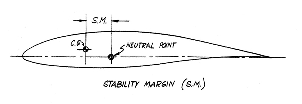
The elevator feel was heavy. If you did hit hard on the nose gear—we called that a $1,500 landing—which was the cost to repair the wrinkled firewall. I flew my original-design pusher with an aft CG at roughly 3% forward of the neutral point. The neutral point definition is that CG location for which there is no stability. The stick had practically no elevator feel.
In an RC airplane, we have only the feel of the transmitter and the flying quality. We can change the CG to get the quality we want without using a lot of exponential.
Most airfoils have an aerodynamic center at roughly 25% of the mean aerodynamic chord (MAC), so that is our reference point. The MAC of a rectangular wing is the chord length, and calculated for a tapered wing, but the average chord length is good enough for us. So from this 25% chord, the CG going forward is good and makes flying easier and stable.
 Going aft with the CG makes the aircraft unstable and harder to fly without exponential; however, this is generally preferred for more aerobatic or 3-D flight. If you go back far enough to hit the neutral point, good luck. You’ve probably lost your aircraft! Fighters use computers to fly aft of the neutral point; humans can’t do it.
The neutral point is calculated and proven in flight or in a wind tunnel. For light aircraft certification, the aircraft aft CG is at least 5% ahead of the neutral point. I flew my tail-heavy pusher roughly 3% forward of this, resulting in no stick feel and it was sensitive.
I had a Stinger 120 that I nearly lost because of an aft CG. Plans show the CG range of 28% to 33% and I was at 33%. It was all I could do to get it back in one piece. My Giant Stinger plans show the CG of 30% to 33% and I fly it at 25%. The full-scale Reno F1 racer rules state a CG of 8% to 25%. Note that Reno racers have small horizontal tails.
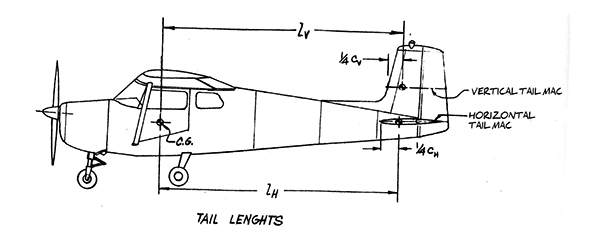
What controls this and how can we change it? It’s the horizontal tail size! The larger the area of the horizontal stabilizer, the more forward and aft CG at which you can be safe. Increasing the horizontal tail moment arm (Lh), like sailplanes, will also move the neutral point aft.
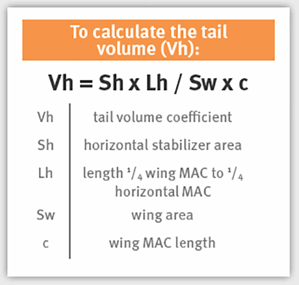
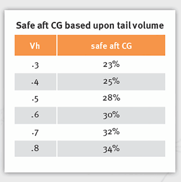
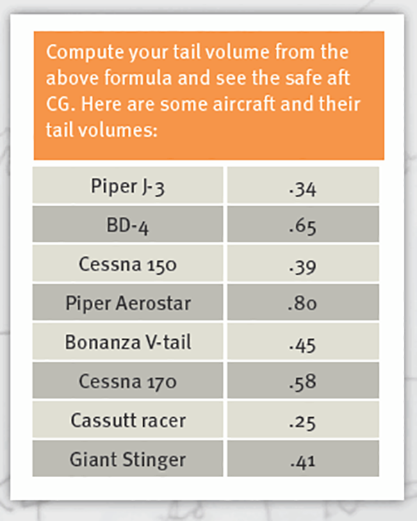
The horizontal area is called the tail volume and boils down to a relative number. It is not hard to calculate this volume and another formula tells us what the most aft useable CG is. I have combined them to save some math and make it easy. The following chart gives us the safe aft CG for the horizontal volume (Vh).
CG is important to the enjoyment of flying our aircraft. If your CG is between 20% and 25%, you should be good. Forward or aft of this range is not so good and aft of 30% could end your day of flying!
The last thing you should do is mount the batteries to achieve the CG you want. In my pusher, a tail-heavy aircraft, I mounted the battery and some lead in the nose. When I designed structure on the Ted Smith Aerostar, last built by Piper, I designed the battery box in the aft side of the baggage compartment. The compartment is at the wing’s TE.
With people and engines forward of the CG, the aircraft is nose heavy and two batteries were mounted in the tail cone aft of the horizontal stabilizer! It is typical to locate the battery last in light aircraft. You can also add some horizontal stabilizer span to your aircraft, increasing the horizontal area, to move the neutral point. You have time and money in your aircraft, now finish your aircraft to fly the way you want.
—Stan Burak
Going aft with the CG makes the aircraft unstable and harder to fly without exponential; however, this is generally preferred for more aerobatic or 3-D flight. If you go back far enough to hit the neutral point, good luck. You’ve probably lost your aircraft! Fighters use computers to fly aft of the neutral point; humans can’t do it.
The neutral point is calculated and proven in flight or in a wind tunnel. For light aircraft certification, the aircraft aft CG is at least 5% ahead of the neutral point. I flew my tail-heavy pusher roughly 3% forward of this, resulting in no stick feel and it was sensitive.
I had a Stinger 120 that I nearly lost because of an aft CG. Plans show the CG range of 28% to 33% and I was at 33%. It was all I could do to get it back in one piece. My Giant Stinger plans show the CG of 30% to 33% and I fly it at 25%. The full-scale Reno F1 racer rules state a CG of 8% to 25%. Note that Reno racers have small horizontal tails.
What controls this and how can we change it? It’s the horizontal tail size! The larger the area of the horizontal stabilizer, the more forward and aft CG at which you can be safe. Increasing the horizontal tail moment arm (Lh), like sailplanes, will also move the neutral point aft.
The horizontal area is called the tail volume and boils down to a relative number. It is not hard to calculate this volume and another formula tells us what the most aft useable CG is. I have combined them to save some math and make it easy. The following chart gives us the safe aft CG for the horizontal volume (Vh).
CG is important to the enjoyment of flying our aircraft. If your CG is between 20% and 25%, you should be good. Forward or aft of this range is not so good and aft of 30% could end your day of flying!
The last thing you should do is mount the batteries to achieve the CG you want. In my pusher, a tail-heavy aircraft, I mounted the battery and some lead in the nose. When I designed structure on the Ted Smith Aerostar, last built by Piper, I designed the battery box in the aft side of the baggage compartment. The compartment is at the wing’s TE.
With people and engines forward of the CG, the aircraft is nose heavy and two batteries were mounted in the tail cone aft of the horizontal stabilizer! It is typical to locate the battery last in light aircraft. You can also add some horizontal stabilizer span to your aircraft, increasing the horizontal area, to move the neutral point. You have time and money in your aircraft, now finish your aircraft to fly the way you want.
—Stan Burak
[email protected]
Image
[email protected]
Image
Sources:
R/C Model Aircraft Design Andy Lennon, author
Light Airplane Design
L. Pazmany, author
Design for Flying David B. Thurston, author
Model Aircraft Aerodynamics Martin Simons, author
Airplane Performance Stability and Control Courtland Perkins and Robert Hage, authors
CENTER OF GRAVITY
How to DETERMINE YOUR CG
Image
Image
Image


Comments
Going to add this to our Club
Going to add this to our Club (1591) info page on our website. Thanks.
Ted Smith Aerostar
Hi Stan,
Nice to read here that you worked on the Ted Smith Aerostar! So did I! I worked for him back in 1967 when the company was located at the north end of Winnetka Ave. in the San Fernando valley. My time there was spent making the first splash tooling for the engine nacelles to be used for stretch forming the skins for the Aerostar. Ted would come by and look my work over. He was a perfectionist, and I was just 22 years old, had excellent eyesight, and steady hands to where I built all the lofting contours from computer print outs, one station at a time. That work convinced me to go into industrial design at school. I also helped with mechanical testing in wing loading, pressurization, coupon tests, air induction system, cockpit design.
Ted also had a hanger at the north west corner of Van Vuys airport behind Clay Lacy and Bud Walden Aviation. Often times we would build the smaller parts,bring them to the hanger, install them on the Aerostar and have them flight tested the same day. Fun times knowing I had a hand in helping to build what was at the time the worlds fastest light weight twin!
Kindest regards,
Gary Filice
Thousand Oaks Soaring Society
AMA478997
FA3P3LRHAK
Great article!
Great article!
Center of Gravity
This article is not much use to 99% of RC flyers. There is some mathematics that is likely beyond the understanding of most modelers. Also there are terms in the formulae that are undefined. Most have heard of the "Mean Aerodynamic Chord", but if the wing is anything other that a rectangular shape there is no method stated as to how to find that.
Also the term "Center of Gravity" in this context is misleading, even though almost everyone uses it. What is actually being discussed is the fore and aft balance point. The actual "Center of Gravity" is a theoretical point in the aircraft, which if you could suspend it from, would have the airplane level. Neither leaning fore or aft, port or starboard.
Most flyers/modelers will use the balance point identified by those that built the airplane. Whether it is a ready to fly, ARF, or kit. One hopes that someone built and flew the airplane to test the balance point. Certainly many flyers will use a different balance point than the original spec.
It would be better to read articles that are usable by modelers that are not engineers.
CG
You define L(h) as 1/4 chord of wing to 1/4 chord of stab, yet your drawing has it as CG to 1/4 chord of stab.
Long time Model Aviation columnist and career aerodynamicist Ron van Putte had a more definitive treatment to obtain MAC's and correct CG location for conventional, canard and delta configurations in the July through October 1988 issues of Model Aviation.
Add new comment