
Written by Heath Bartel
As seen in the August 2021 issue of Model Aviation.
RC Combat
CHOOSING ELECTRIC POWER SYSTEM components for RC Combat can be an overwhelming task, given the wide array of components that could be combined in several ways. I will share the process that I use to select electric power system components. This process can also be applied to the design of an electric power system for any type of model.
When designing a power system, the first step is to identify the fixed components, any additional restrictions, and the desired amount of power. The fixed components could be specified by the class of Combat or simply by the desire to use components that the builder has on hand.
Combat rounds are 5 minutes long with a 90-second, pre-round launch window. When designing a power system, the goal is to provide power for the full 5 minutes of high-energy Combat, lower-powered flight before starting Combat, and some reserve. An aggressive setup would be designed to fly for 5-1/2 minutes, while a more conservative setup would be designed to fly for 6 minutes.
Slow Survivable Combat (SSC) specifies a Master Airscrew 8 × 3 propeller spinning no faster than 17,500 rpm. With the propeller defined by the class rules, three power system components remain: the battery, ESC, and motor. Because the rpm is specified, the next step is to identify a motor and battery combination that will spin the Master Airscrew 8 × 3 propeller slightly faster than the desired rpm. Ideally, the rpm should be slightly more than the limit at full throttle. The rpm is then fine-tuned by reducing the full-throttle endpoint.
Electric motors have a Kv rating that specifies how fast the motor will spin when one volt is applied with no load. If an 11.1-volt battery is used with a 1,000 Kv motor, the unloaded rpm will be 11,100 (11.1 × 1,000). However, when a propeller is attached, the load will cause the motor to spin slower. The exact amount depends on how much torque the motor can produce relative to the size of the load and how much the battery voltage drops when a load is applied.
To build a practical power system, it is unnecessary to calculate exactly how much slower the motor will spin. Instead, a test system can be assembled with a reasonably high probability of working by multiplying the target loaded rpm by 105% and 120%. For SSC, the desired loaded rpm is 17,500, so the target unloaded rpm range would be 18,375 rpm to 21,000 rpm.
Let’s consider a real-world example using the data contained in the table shown. I have two motors. One is 1,450 Kv and one is 1,100 Kv. I also have two batteries. One is 11.1 volts and the other is 14.8 volts. This gives me four possible combinations with a predicted unloaded rpm ranging from 12,210 to 21,460. I can eliminate three of the four combinations because they fall outside of the target unloaded rpm range. Testing confirms that the 1,450 Kv motor produces a loaded rpm of 19,740, which is slightly above my target of 17,500.
When a candidate battery and motor combination have been selected, the watts need to be checked to ensure that the motor is not being overloaded. The amount of power used by a motor is measured in watts. The D3536/5 has a measured 453 watts, which is well within the rated maximum of 655 watts. As a result, I can be confident that, with reasonable airflow, the motor will not overheat when it is used with a 14.8-volt battery and a Master Airscrew 8 × 3 propeller.
With the propeller, motor, and battery voltage selected, the correct ESC can now be determined. The ESC controls how fast the motor spins and is rated by its capacity to transfer power from the battery to the motor in amps. Because the maximum amps from the selected motor and battery is 30.58 amps at 14.8 volts, an ESC rated for a minimum of 35 amps and 14.8 volts (4S LiPo) will be needed.
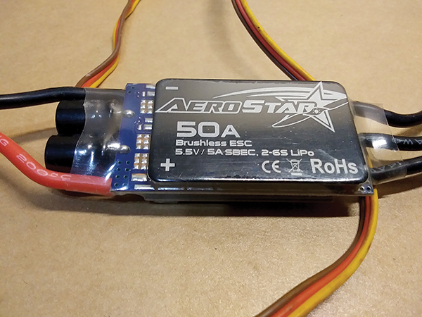 The 50-amp AeroStar ESC.
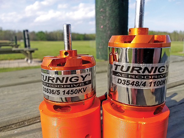 The D3535 1,450 Kv and D3548 1,100 Kv motors.
The final step is to choose the battery capacity. A 14.8-volt battery has been selected, but the capacity still needs to be determined. The throttle curve is adjusted so that at full throttle stick, deflection equals 89% of the total throttle. This result is the desired 17,500 rpm and reduces the load to 24 amps. The required battery capacity can be calculated with the following formula:
Capacity in amp hours ÷ amps × 60 = minutes of powered flight
Using the known values of 24 amps and 6 minutes gives a required capacity of 2.4 Ah. The common-size batteries that are roughly 2.4 Ah are 2.2 Ah and 2.65 Ah. The 2.2 Ah would result in a flight time of 5-1/2 minutes, while the 2.65 Ah would result in a flight time of 6.6 minutes. The 2.65 Ah battery is the safer choice because it provides a pilot more reserve, ensuring full rounds at full power. The 2.2 Ah battery is an aggressive choice that, although lighter, could cause a pilot to land early.
This process can be applied to any class of Combat. For the E1000 class, the battery is specified as 1 Ah, 11.1 volts, while the propeller, motor, battery, and rpm are open. As the battery capacity, voltage, and desired flight time are known, the required amps can be calculated as 10 amps for 6 minutes and 12 amps for 5 minutes.
Based upon this, a 20-amp ESC is a good choice. Two components remain: the propeller and motor. If a larger propeller is desired, a lower Kv motor will be selected. If a smaller propeller is used, a higher Kv motor will be selected.
Following a structured approach to electric power system design will ensure that the system meets the requirements while avoiding smoking motors or overheated ESCs.
The D3535 1,450 Kv and D3548 1,100 Kv motors.
The final step is to choose the battery capacity. A 14.8-volt battery has been selected, but the capacity still needs to be determined. The throttle curve is adjusted so that at full throttle stick, deflection equals 89% of the total throttle. This result is the desired 17,500 rpm and reduces the load to 24 amps. The required battery capacity can be calculated with the following formula:
Capacity in amp hours ÷ amps × 60 = minutes of powered flight
Using the known values of 24 amps and 6 minutes gives a required capacity of 2.4 Ah. The common-size batteries that are roughly 2.4 Ah are 2.2 Ah and 2.65 Ah. The 2.2 Ah would result in a flight time of 5-1/2 minutes, while the 2.65 Ah would result in a flight time of 6.6 minutes. The 2.65 Ah battery is the safer choice because it provides a pilot more reserve, ensuring full rounds at full power. The 2.2 Ah battery is an aggressive choice that, although lighter, could cause a pilot to land early.
This process can be applied to any class of Combat. For the E1000 class, the battery is specified as 1 Ah, 11.1 volts, while the propeller, motor, battery, and rpm are open. As the battery capacity, voltage, and desired flight time are known, the required amps can be calculated as 10 amps for 6 minutes and 12 amps for 5 minutes.
Based upon this, a 20-amp ESC is a good choice. Two components remain: the propeller and motor. If a larger propeller is desired, a lower Kv motor will be selected. If a smaller propeller is used, a higher Kv motor will be selected.
Following a structured approach to electric power system design will ensure that the system meets the requirements while avoiding smoking motors or overheated ESCs.
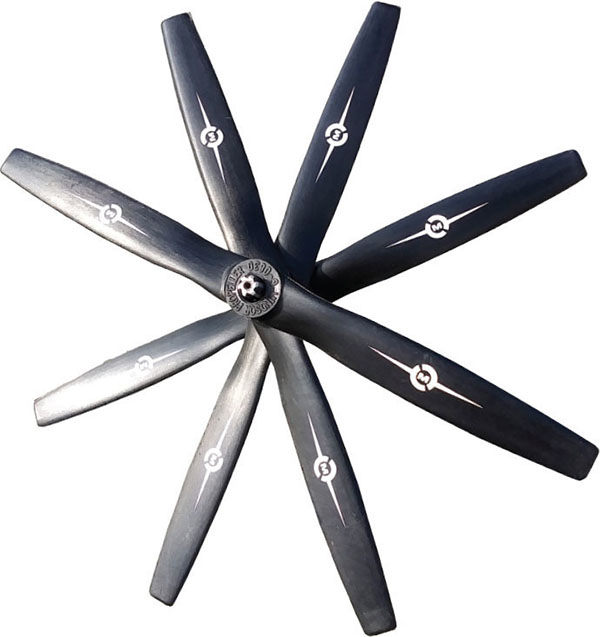 The Master Airscrew 8 × 3 propeller.
SOURCES:
Radio Control Combat Association (RCCA)
www.rccombat.com
Master Airscrew
(916) 631-8385
www.masterairscrew.com
The Master Airscrew 8 × 3 propeller.
SOURCES:
Radio Control Combat Association (RCCA)
www.rccombat.com
Master Airscrew
(916) 631-8385
www.masterairscrew.com
Image
Image
Image
Image


Comments
Glad to see this finally
Glad to see this finally getting some traction. We did am SSC demo at NEAT Fair for a few years back 12 or so years ago. I came about the power system exactly the same way this article describes.
Electric Power System Design
As a retired Algebra teacher, I would like to suggest a better format for your equation on page 4. You have: Capacity in amp hours ÷ amps x 60 = minutes of powered flight. I suggest:
(Amp hours ÷ amps) x 60 = minutes of powered flight. ( the quantity)
Your equation can be misunderstood that the Amp hours is divided by amps x 60
Great Info!!
Great Info!!
Add new comment