
Written by Clark Salisbury
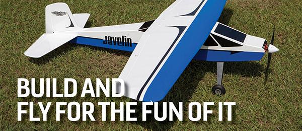
Build this easy-flying, three-channel airplane
As seen in the October 2021 issue of Model Aviation.
At a Glance

Bill of Materials
(6) 3/32 x 4 x 36 balsa sheets (12) 3/16 x 2 x 36 balsa sheets (6) 1 x 2 x 12 balsa blocks (1) 1/4 x 1/4 x 36 balsa strip (4) 3/8 diameter x 36 wood dowels (3) 5/16 diameter x 36 wood dowels (8) 1/2 x 4 x 12 balsa blocks (1) sheet of 1/8 aircraft or poplar plywood 12 x 24 (1) sheet of 3/16 poplar or aircraft plywood 12 x 24 (4) rolls of covering material, three colors plus clear for the windows (2) Sullivan 5 x 1.75 wheels No. S883 or 4.75-inch diameter foam Multiplex FunCub wheels (1) 12-inch #4-40 threaded rod (1) package Du-Bro standard hinge (DUB116) (4) Du-Bro ball links with hardware #4-40 (DUB2161) (1) Du-Bro control horn (DUB237) (1) package with a formed windshield, landing gear, and instrument panel gauges (available from the author) (2) #8-32 x 2 machine screws (4) #8-32 hex nuts (4) #8-32 nylock nuts (10) #8-32 nylon pan head x 1-inch screws (10) #6-32 nylon pan head x 3/4-inch screws (2) 1/16 diameter x 12-inch steel rods
Specifications
Wingspan:71 inches Length: 57 inches Height: 21 inches Weight: 4.5-plus pounds
Test-Model Details
Motor used:E-flite Power 25 or equivalent 1,250 Kv brushless outrunner ESC: E-flite or equivalent 40-amp Battery: 3S 2,100 mAh LiPo battery Radio system: Fourchannel radio and receiver Servos: Hitec HS-85BB Propeller: Electric 11 × 5.5
Order Plans from AMA Plans Service

DOWNLOAD FREE PLANS!
Full-size plansTiled plans
Cutting Out the Parts
As seen in Figure 1, cut out all of the parts that are depicted on sheets two, three, and four of the plans. All you will need is a glue stick to glue those patterns onto either the balsa, pine, or plywood as called out. As large as this model is, you will still need to glue some parts together. The fuselage sides are 7 inches wide, but you only have 4-inch balsa to work with, so you will have to splice the balsa together to give you an 8-inch width. Parts such as the fuselage sides and the wing ribs that require two or more to be built should be cut stacked to save some time. Be sure to cut on an angle with your scroll saw, as shown on certain parts, such as the fuselage formers and wingtips. Notice that there are a number of holes to be drilled, and some of the holes will need to be threaded.


Building the fuselage
As shown in Figure 2, glue the plywood landing gear mount to the rear balsa floorboard. Pin these to a building board over waxed paper as they dry. My photo does not show the big slot in the landing gear mount because I cut it out later to save some weight. Glue formers F2 and F3 to the floorboard and to the front right fuselage side panel, as shown in Figure 3. Use a square to make sure the fuselage side panel is perpendicular to the floorboard. Ensure that you have laminated F2 together for a total thickness of 3/8 inch. Figure 4 shows gluing the left front side of the fuselage to the floorboard and the F2 and F3 formers, again making sure that everything is square. The upper front and rear wing mounts and F4 are also glued in place in this step. Note that it is 3/16-inch plywood and the rear edge of the fuselage side panels should only cover half the thickness of this former. The rear fuselage side panel pieces will cover the other half. Figure 5 shows the glued-in instrument panel and the F1 motor mount. Use elastic bands to hold the side panels against these parts as they dry. This is a great time to glue in the gauges on the back side of it after you have painted the front side of the instrument panel. I painted the instrument panel dark gray, although everything else in the cabin was later painted black. In Figure 6, the motor is screwed in place using the provided screws. This is a good time to test-fit the nose piece to see if it aligns with the motor shaft. Glue in a 1/4-inch square balsa piece, 2-3/8 inches long, in front of the motor mount on both sides as shown. Glue in the front cowling top piece as shown in Figure 7, using T-pins to hold it in place against the fuselage side panels. Glue in former F1A, which is located just ahead of the instrument panel, and glue the battery cover attachment plate to the center of F1A. Figure 8 shows the battery cover with the battery cover formers glued in place. Figure 8A shows the same part, with two toothpicks added to retain the front side. When it is dry, drill two 1/16-inch diameter holes in the F1 motor mount for the toothpicks to enter. Figure 9 also shows the lower fuselage doublers pinned in place and glued. The front nose piece mount is also glued in place, along with the two inserts, which are drilled and tapped to a #6-32 thread. Those holes must line up with the holes in the pine nose piece. In Figure 10, the drive battery box is glued together. This box only fits the E-flite LiPo battery in the bill of materials. You can glue this together around the battery itself, but leave some clearance all around the battery. Figure 11 depicts the battery box glued in place in the front of the fuselage, directly to the back side of the F1 motor mount and F2. The AAA battery holder for the LED lights is shown in Figure 12. It first needs to be screwed to the square plate made of 1/8-inch plywood then, as shown in Figure 12A, glue the triangular gussets to the bottom of the square plate. Glue this entire assembly to the top of the battery box that was glued into the fuselage in Figure 11. Make sure it does not interfere with the battery cover when it is put in place with the toothpicks sticking into the motor mount. In Figure 13, the front half of the fuselage lays directly on a 48-inch straight line, which has been drawn on the building board. The front half of the fuselage should be pinned down in this step.


Building the Tail Feathers
In Figures 25 and 26, the construction of the horizontal stabilizer and the vertical stabilizer with the elevator and rudder attached is complete. These are done on your building board using waxed paper on top of the plans then pinning and gluing all of the pieces together. When all of the pieces are done, you will need to slot the indicated parts to accommodate the nylon hinges. After the hinges are in place, drilling a 3/16-inch hole through the balsa and the hinge and filling the hole with epoxy will ensure that the control surfaces never separate in flight. In Figures 27 and 28, the four LED lights have been epoxied in place. First, drill 3/16-inch diameter holes in the horizontal stabilizer at a 45° angle. The angle is so that the LEDs will point toward the vertical stabilizer and light up the tail at night. In Figure 28, the wires are soldered to the leads of the LEDs. Groove the balsa deep enough for the wires. LEDs only work with electricity flowing in one direction, so the short lead is positive and the long lead is negative. I used yellow wires for the positive leads and black wires for the negative leads. You need to solder the yellow wires together and the black wires together. They should all end up at the AAA battery holder in front.Wheel Pant and Seat Construction
Figures 29 and 30 show the balsa parts cut out, assembled, and glued together to form the wheel pants. Make sure that you build a left and a right wheel pant. The plywood part of the wheel pant will be closest to the center of the airplane. I have included optional cutouts on the plans sheet to lighten the wheel pants. If you are going to use an opaque covering material on this model, go ahead and make the cutouts. It will save some weight and you won’t see the holes. If you are using a semitransparent covering material, do not make the cutouts. The holes will be visible and it will look terrible. You will need to sand these wheel pants to round the corners. Make sure that you sand the left and right the same amount to look good later. When they are done, you can drill the 3/8-inch diameter hole in the front of each wheel pant to accommodate the LED and its holder, which will be glued in place after the covering is complete. Figure 31 shows the seats glued together. I painted everything on the inside of the cabin black, but my wife had some nice dark gray cloth that I glued to the flat part of the seats, and it looks awesome. I also painted the instrument panel that same dark gray.Wing Construction
Figure 32 shows the completed right wing half. I actually used the wing halves from a former model that I built six years ago. My plans only allow you to build one wing at a time, so build the right wing first. It is constructed on the building board by pinning the leading edge (LE; a 3/8-inch diameter wood dowel) to the waxed paper-covered plans. The ribs are glued to that LE one at a time, starting on the outside of the wing.


Finishing the Airplane
Although not shown, the wing struts need to be completed. Insert 1-1/8-inch long pieces of #4-40 threaded rod into each hole at both ends of the wing struts and epoxy them in place. The struts should be covered with yellow if you are following my color scheme. Figure 36 shows the battery box cross support glued in place. Note that it is cut in parts, and that one side has a hole to accommodate the ESC wire. At this point, your receiver needs to be wired in, with servos attached and the ESC in place. Do not install the propeller yet for safety. Check your radio transmitter and make sure that all of the servos go in the direction that you want them to for rudder and elevator control. I had elevator control as forward, backward, and side motion on the right stick that controls the rudder. Make sure that the left stick pushes forward to activate the throttle. Take the leads on your AAA battery holder (for your LEDs) and lengthen them so that they can go back into the cabin area approximately 6 inches to later solder all of your LED wires together. Figure 37 shows the seat support box glued together. I later painted this black. In Figure 38, the seat support box is in the cabin and the seats are sitting on top of it. Note that 1/4-inch square balsa strips need to be glued to reinforce the top of the fuselage above the cabin windows.
Flying the Airplane
After building this airplane, it will be hard to push yourself to fly it because you have put so much hard work into its construction. It was tough for me; however, the real joy comes from watching this model fly. The tail skid actually helps this airplane take off straight if you are flying from grass because it tends to drag through the blades of grass, keeping it straight. I needed no rudder correction on the maiden flight. I gently eased the throttle forward and it took off in roughly 25 feet, although I was only at approximately 2/3 throttle. Let the model climb out for a couple of seconds then start your turn. Your first turn won’t require any elevator input. When you are flying level, a little up-elevator needs to be added with rudder to make a level turn. The airplane makes pretty, smooth turns. I brought the throttle back even more for cruising to half throttle or less. This airplane is just a joy to fly. My maiden flight was on a perfectly calm day, which made for graceful flying. My wife’s video of those maiden flights is very smooth. At my home in Utah, at a 4,600-foot elevation, the airplane still has plenty of power. I recommend flying in a large area. Because the airplane is large, it is deceptively fast. I did not design this airplane to be aerobatic, so I cannot comment on its ability to do loops. It probably will, but I haven’t yet tried any. Complete dead-stick landings are fun. The airplane tracks as though it is on rails when you pull the throttle all the way back and let it turn into a glider. Again, all of that dihedral makes this possible. I did both maiden flight landings dead stick, just for the fun of it. Have fun!


Comments
plan error
sheet 1 of full size plan is wrong. Not Sky Flieger it's a Jap scale fighter Ki 27
Plans are nice, but laser cut parts would be nicer!!
Plans are nice, but laser cut parts would be nicer!! This one is just my size.
sky Flieger plans
What are the sizes of the plans?
Add new comment