
Written by Derek Micko Build one of the fastest propeller-driven aircraft ever flown As seen in the October 2020 issue of Model Aviation.

The Model
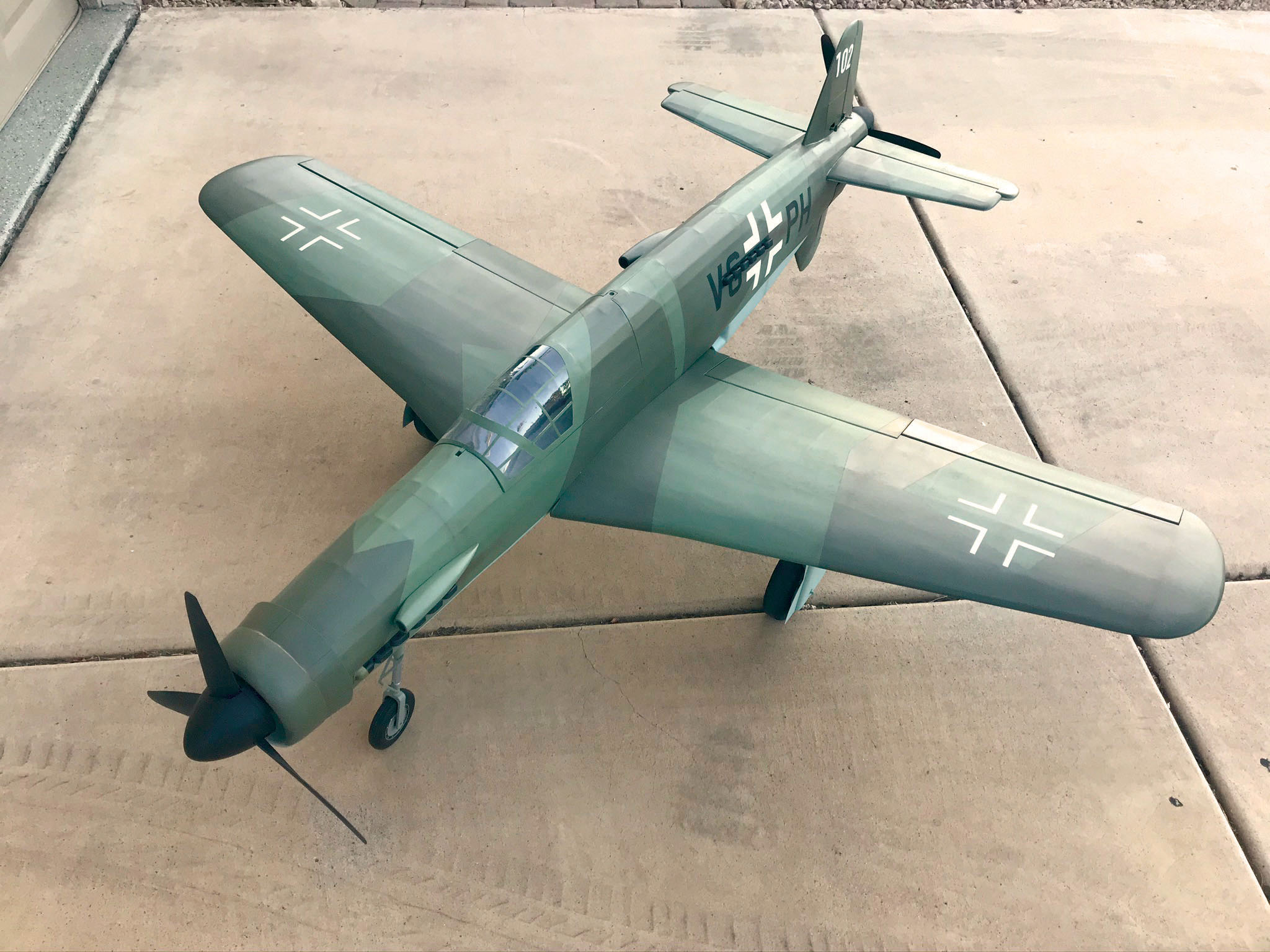
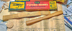
Similar to some of my previous designs (the Bearcat and I-16 Rata), the 335 is designed with scale outlines but features a stick-and-tissue Free Flight stringer look. The result is an accurate-looking model of the full-scale aircraft but with a lower wing loading for gentler flying. The model features CAD-designed interlocking parts and is built using plywood, light plywood, basswood, and balsa. To help simplify operation, the model can be built powered with only the front motor (tractor) or with both the front and rear motors. The front motor uses a Power 60 motor, 80- to 90-amp ESC, 16 × 8 three-blade propeller, and a 5,000 mAh 6S LiPo battery. This combination offers good flight performance; however, a modeler can add the second motor if he or she wants a twin. The plans are available as a free digital download from Model Aviation online. Should you choose not to cut the parts yourself, Manzano Laser Works sells the parts in a short kit, including an available canopy from Park Flyer Plastics. The spinners are modified versions of Paul Kohlmann’s M.20 design. These and the nose gear file can be found on Thingiverse and can be 3D printed (see "Sources"). Construction details will cover the main points of building the model and are excerpts from the construction manual. The full manual is available for download on Manzano’s website.Horizontal Stabilizer
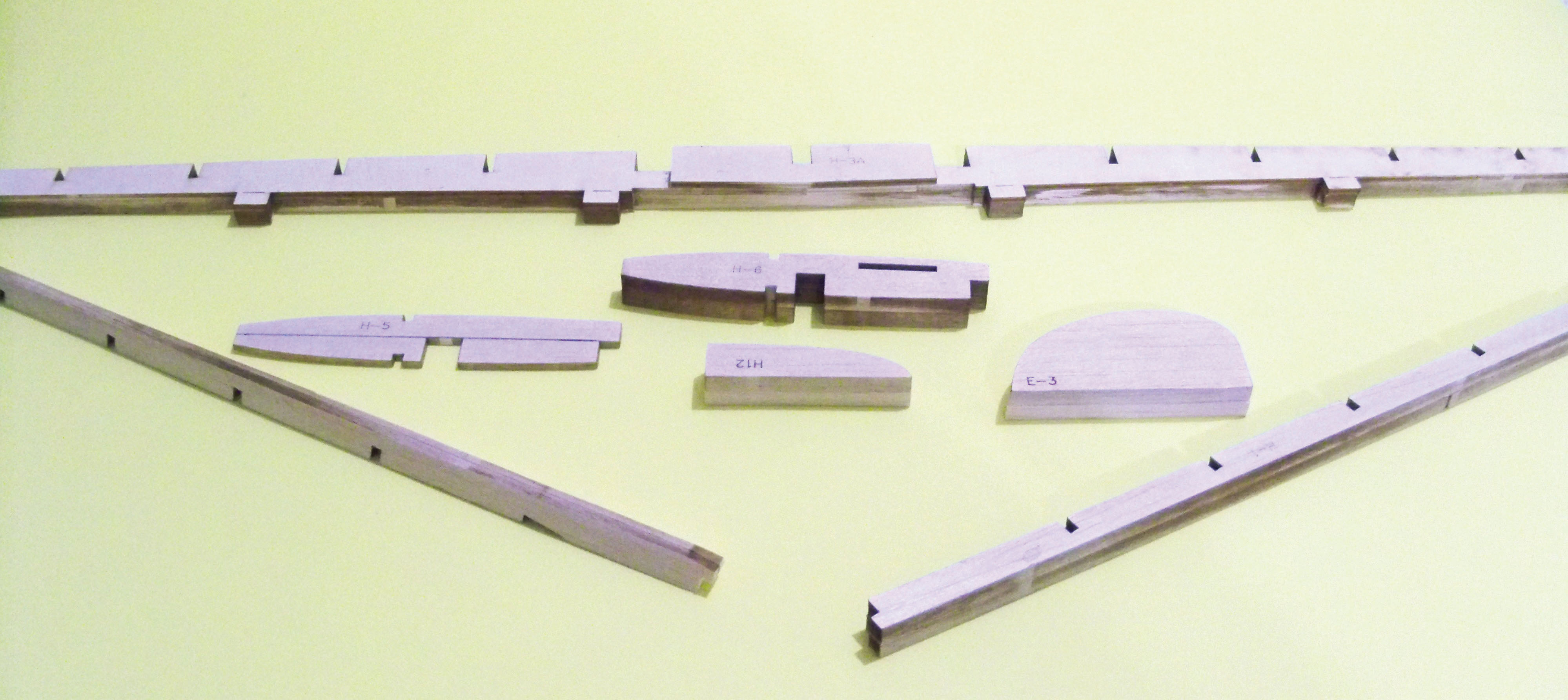
The first item to build is the horizontal stabilizer. On the full-scale aircraft, it had a slight amount of dihedral. The model replicates this, so it needs to be built in halves. The main spar is a lamination of balsa and plywood. These are glued together, as are the tips and the leading edges (LEs). Using the ribs as a guide, bevel the LEs to match the rough contour of the ribs (this will be fine-shaped later). Scrap 1/32-inch balsa shims are cut and glued to the elevator LE then this is tacked in place against the horizontal stabilizer’s trailing edge (TE). Dry-fit the ribs in place, minding the tabs for the elevator mounting plate. When you are satisfied, glue them in place. The elevator TE is made from 1/8 × 1/2-inch medium balsa cut to length and slides into the slot at the rear of the ribs. With one side completed, the assembly is unpinned and the other half is built. A 1/8-inch square basswood stringer is added, and the center section is sheeted with 1/16-inch balsa. The elevators are then cut free and the shims are removed. The horizontal stabilizer and elevator LEs are rounded and contoured, and the tips are added and shaped. There is a slot between H-2 and the stringer where the sheeting is removed (top and bottom). A former (VP-1) will go in this spot later. A er the construction of the horizontal stabilizer is complete, the assembly is sanded and covered. Nitrate and silkspan dope and tissue were used on the prototype. If you are covering with film, lightly sand/scuff the film surface (for paint adhesion) before application.
Image
Image

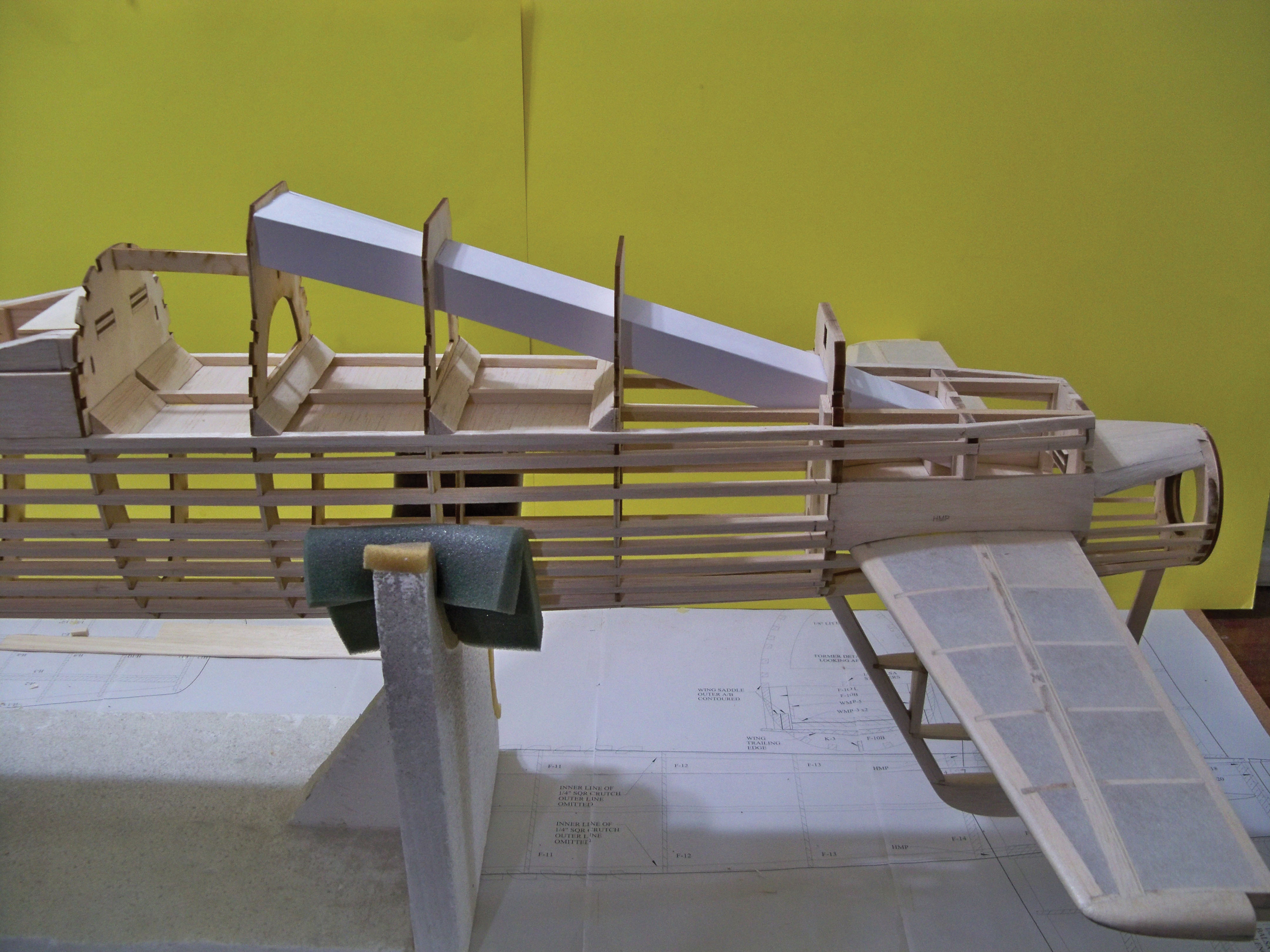
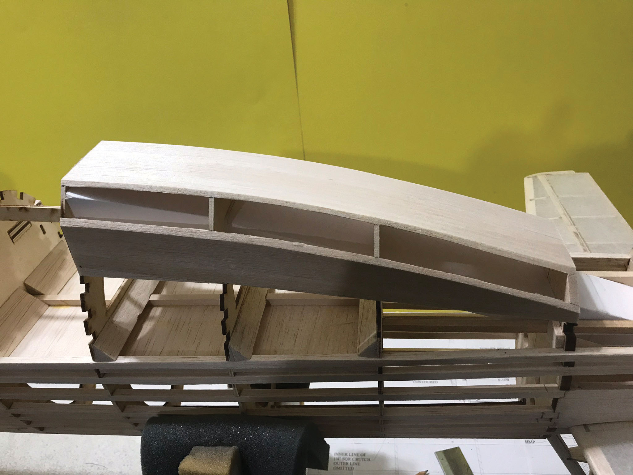
Fuselage—Top Half
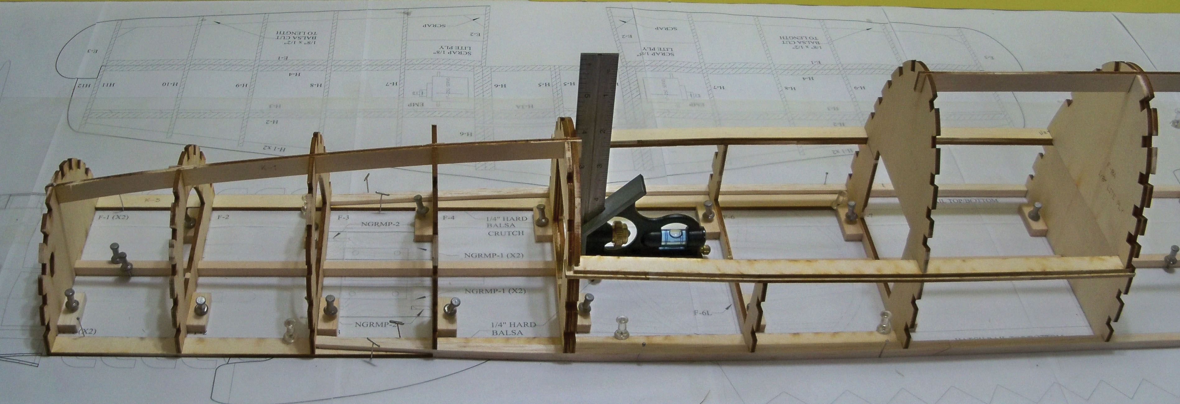
The fuselage top half is next and built over the fuselage top view plans. Several longitudinal stringers make up the crutch. The center stringer (and the rear and center split stringers) are made from 1/4-inch square basswood, and the outer stringers are 1/4-inch square balsa. They slide into a slot in part K-5. Pin these stringers in place over the plans along with the K-5s. Note how the center stringer splits and becomes two at former F-13. Cut the 1/2 × 1/4-inch crosspieces (dashed lines on the plans) and add these either fore or a of the formers then glue the outer stringers to the K-5s. Find parts F-5U/F-5A and F-8U/F8A and orientate them according to the plans, adding 1/32-inch balsa shims between them.Image
Image
Image
Image
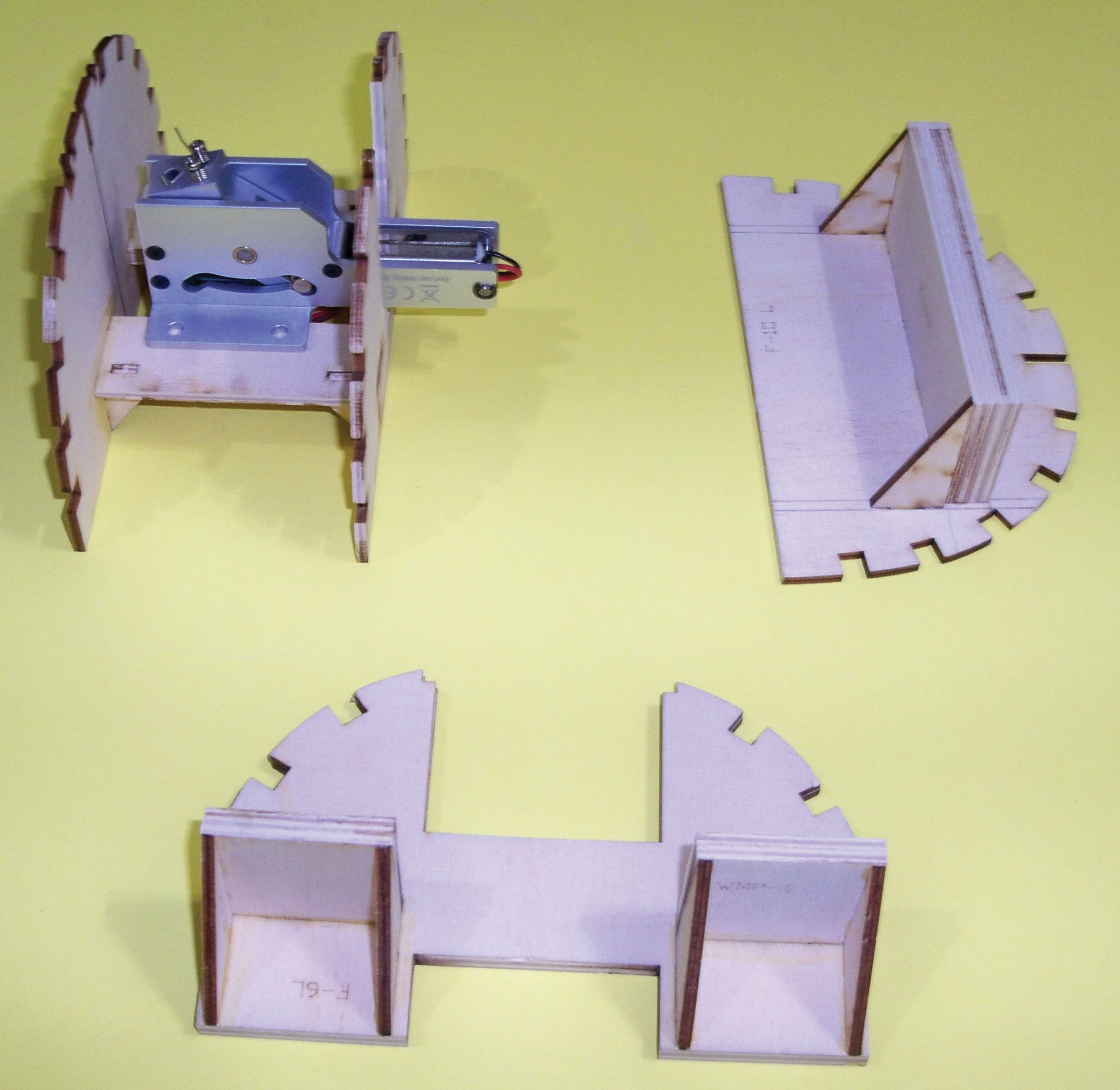
Fuselage—Bottom Half
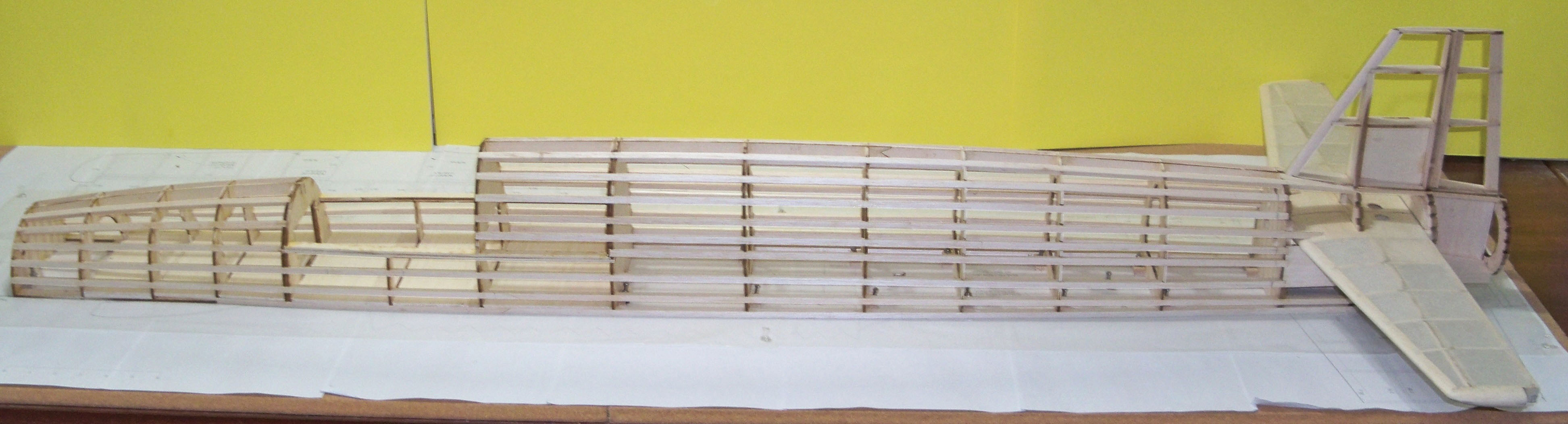
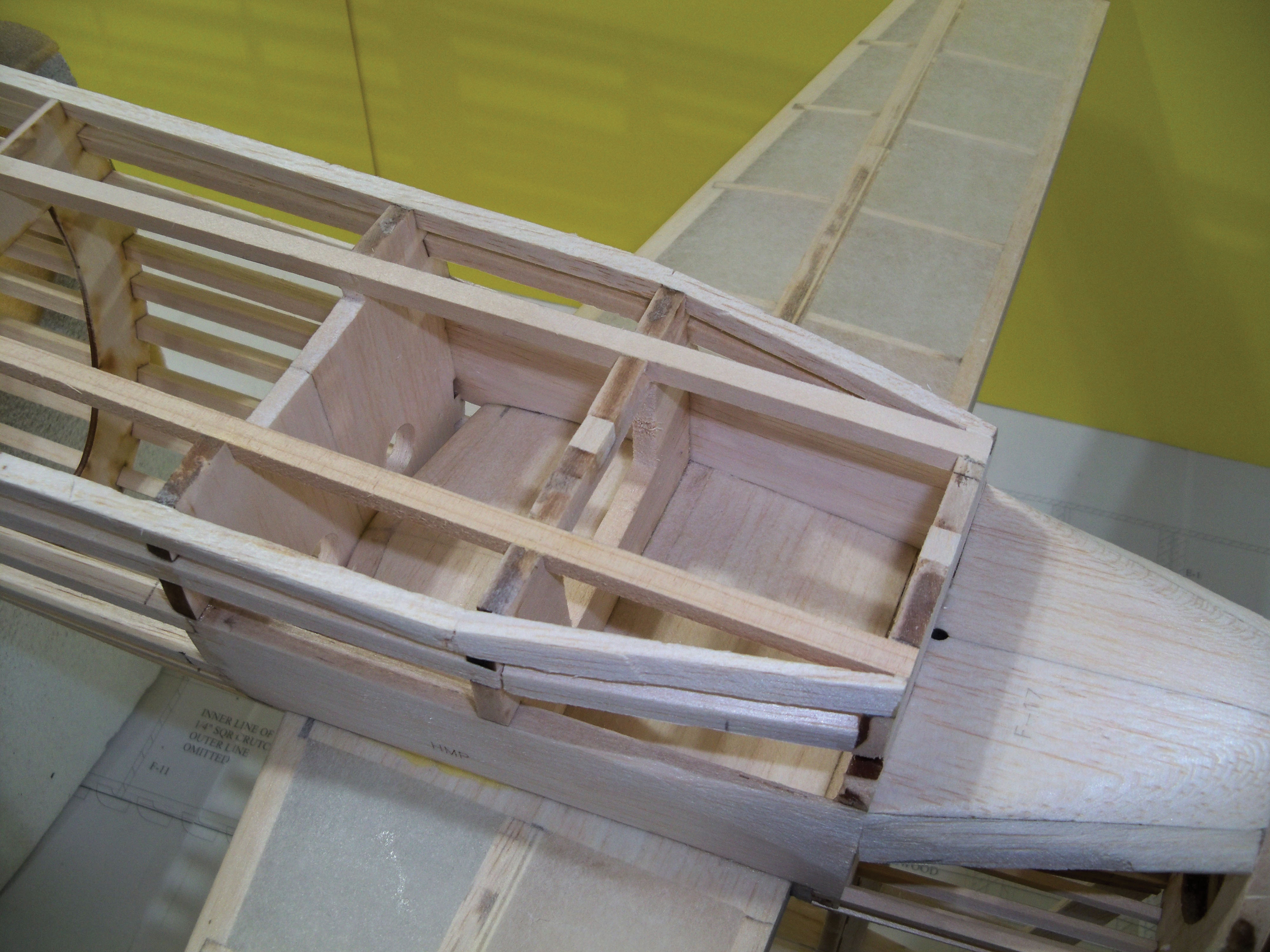
Former F-6L, the wing mounting plates, and the nose gear mounting plate subassemblies are glued together. The forward wing mounting plate (WMP-1) is separated in the middle to allow for the nose gear retraction. The wing mounting plate assemblies tab into F-6L and F-10L and have triangular support parts. The nose gear mounting plates tab into F-3L and F-4L. Test-fit the retract at this time. The bottom (L) formers are added now, as is the cardstock ducting (see the plans). The wing saddles are added next—first A then the additional Bs. The bottom and sides of the belly scoop are from 1/8-inch balsa sheet. Cut and sand the edges to match the angle in the former then add a sheet of 1/4-inch balsa for the quarter-panel trim to match the outline. Glue the six laminates of F-11B (1/4-inch balsa) and one F-11A (1/8-inch light plywood) and sand to shape. The bottom vertical is made the same way as the top, so check that the rib notches on the formers are on the same side. Add V-8B/C. Cardstock will enclose V-13 to V-8C. Add the remaining 1/4-inch balsa and 1/8-inch basswood stringers. Sand overall and fill in the sections as shown on the plans. The main firewall (F-1) is then added, along with the four FWs, and the motor is test-mounted.Cowling
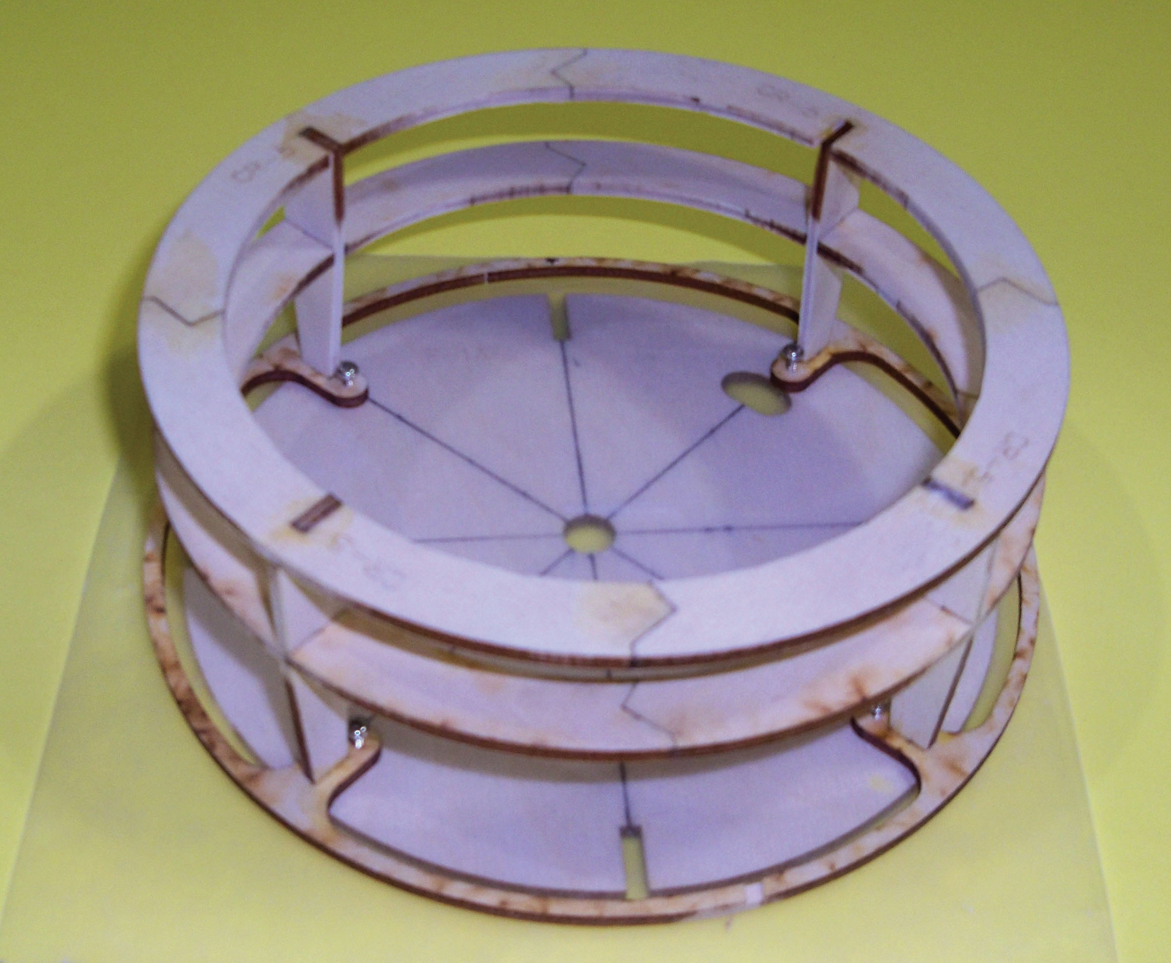
Make the four front cowling rings next, with each ring made from four pieces of 1/4-inch balsa (use the plans for reference). A er the rings are made, they are stacked on top of one another. Make the two center rings from light plywood parts. The ribs (CR-7) are first added to the center rings. Slide them into the notches of the mounting ring (CR-6). Sheeting is added (1/16-inch balsa) to the center section and to the outer section, making the cowling flaps. The front rings (laminates of 1/4-inch balsa) are added, and the assembly is sanded to shape.Wing
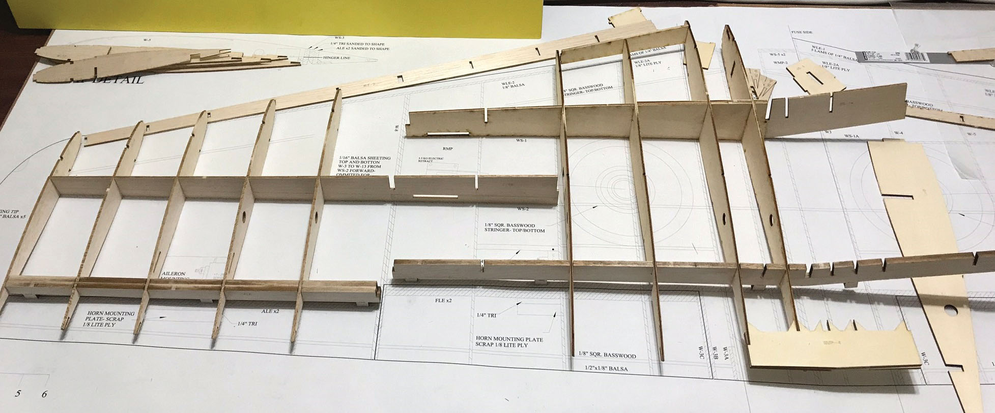
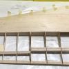
The light plywood main wing spar is joined at the center section with WS-1A (forward of WS-1). The retract plates are from two layers of 1/8-inch plywood and notched into W-6 and W-7/8. Balsa shims (1/32 inch) were added between WS-4 and the aileron LE then tack-glued together. Repeat the process with WS-3 and the flap’s LE. Plane down the top edges of these assemblies to match the rib contour. Wing spar two is similar to the main spars on the Bearcat and Rata. The top portion is balsa with a basswood plank glued to the bottom for rigidity. Pin these assemblies over the plans.Image
Image
Image
Image
Image
Image

Image
Belly Pan
With the wing mounted in place, add the belly pan formers with 1/4-inch balsa triangle stock on each side. Add 1/4-inch square stringers from hard balsa or use BP-1 (see template). Add BP-2 according to the plans, blocking in around the wing mounting bolts with scrap.Main Gear Struts and Doors
If you’re not using commercially available struts, you can make your own. The prototype main gear struts were made from 5/32-inch piano wire utilizing 5/32-inch axles. The gear doors were made from two cross laminations of 1/64-inch plywood. The doors were mounted in the retracted position with the excess length of the axle passing through the door. It is held in place with a 5/32-inch wheel collar. The door’s midsection was secured with a 5/32-inch wheel collar (over the main strut). Refer to the plans for greater details and the parts used.Image
Final Details
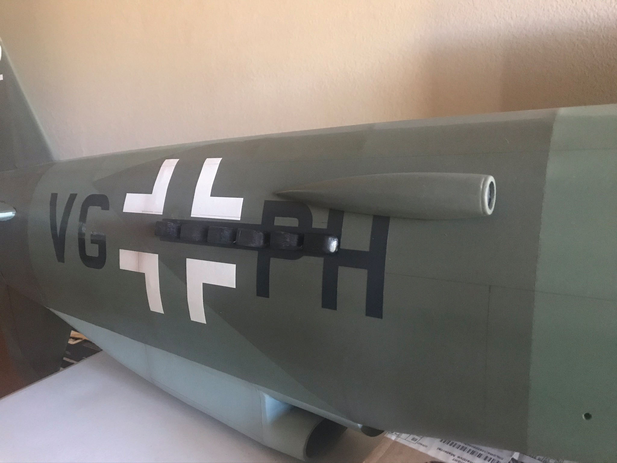
Mount all of the servos in the wing, tail, and fuselage (including the steering servo) and test for the controls to be plus or minus 1/2 to 3/4 inch. Set the flaps for 30° and 45°. Du-Bro E/Z connectors and .062 wire are used to connect all of the control surfaces. The two side scoops are made from six laminates of 1/4-inch balsa with a plywood front ring. Exhausts (24) are made from two laminates of 1/4-inch balsa and a rear plywood ring. The hatch is cut free and mounted according to the builder’s choice. The canopy is then glued on with canopy-safe adhesive. Detail the cockpit to your liking. The prototype performed well with just the front motor; however, a smaller electric motor in the tail can be added (use the regular plywood F-20 for this version). The rear ESC can be routed in the cardstock ducting. Balance the model according to the plans. The model can be covered/finished as the builder prefers. The prototype was covered with medium silkspan and nitrate dope. A er covering, add the F-11 A/B/C assembly. Paint it to match the full-scale aircraft: Reichsluftfahrt Ministerium (RLM) paint designation 02 (gray) for the wheel wells, cowling insides, and wheel hubs; RLM 81 and 82 (brown-violet and light green) for the fuselage and wing top; and RLM 65 (light blue) for the bottom surfaces. Commercial spinners can be used or more scale-like ones can be printed using the link in the "Sources." Additional details can be added according to the builder’s preference.Flying
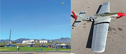
Before the first flight, perform a range check, test the gear, and check that the controls are in the correct direction. Takeoffs are straightforward and eased by the tricycle gear. Climb out steadily. Retract the gear and trim as needed. The prototype flew well between 1/2 and 3/4 throttle. Rolls are smooth and stalls are straightforward. The nose drops and one wing might as well, but it does not snap and you can recover from this with power. On approach, gently reduce power on the glide-slope before bringing the throttle to idle just before touchdown. The initial testing did not require using flaps. The model slows down nicely, and touchdowns are smooth.Image


Comments
Dorinerr Pfiel Do335
How do i download free plans as stated in this months magazine?
Plans
Hi Paul. You should be able to find the link to the plans at the top of the page.
Wrong plans
Wrong plans
Download for sheets 1 ans 2 dont work
Hello! I tried downloading sheets 1 and 2. The links give you the Volmer plans instead
Craig
DO-335
Can this plan or does this plan have the option to modify the twin seater DO-335?
Can the tiled plans be printed in A4 size paper
Great looking plane,can the tiled plans be printed in A4 size paper or are they only suitable for letter size?
Add new comment