Several years ago, Paul Kohlmann and I discussed working together on a joint project—designing and building two aircraft that had fought each other in combat but were perhaps not often modeled. The aircraft chosen were the I-16 Rata (mine) and the Curtis P-36 Hawk (Paul’s).
These models were featured in the October 2018 issue of Model Aviation and the articles were jointly titled, "Fighter Face-Off." (See the "sources" list.) We had such a great time during the process that we wanted to do it again. Several years passed and other projects were built before we decided that it was time to do another collaboration.
I had recently returned to building several smaller projects and convinced Paul to do the same. He mentioned that he’d like to do a Brewster Buffalo in the British or American colors and asked if I could find an opponent. Wanting to keep with the idea of doing a "lesser-modeled" aircraft, I passed on the Zero but was able to find the Ki-27 Nate. We chose to do them as park flyers, keeping the wingspan to 30 inches with a power setup of 18- to 24-gram motors. With the aircraft and size determined, I set about learning more about the Nate.
The Ki-27 was designed by the Nakajima Aircraft Company, first flying in 1936 and entering into service a year later. The aircraft featured a radial engine with two 7.7mm machine guns that fired through the propeller using interrupter gear. Although not as fast as some of its contemporaries, the Nate (as the Americans dubbed it) was extremely agile. The Nate first saw combat against the USSR in 1938, where it initially gained air superiority over the I-15 biplane and early versions of the I-16.
The Nate’s maneuverability and better-trained Japanese pilots held their own until more advanced and up-gunned I-16s came onto the scene. The Ki-27 was the frontline fighter up to and during the beginning of World War II, where it faced off against the Buffalo with mixed results. As better Allied aircraft came into service, the Nate was replaced by the Ki-43 Oscar; however, some were used at the end of the war as both fighters and Kamikaze aircraft, and losses were significant.
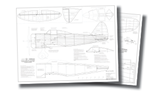
The model’s construction is similar to a large Free Flight (FF) model. In fact, with some slight modifications, it could be built as a rubber-powered model (the RC airframe weighs roughly 68 grams). The prototype flies with an 18-gram brushless motor on a 2S 450 mAh LiPo battery pack spinning a 7-inch propeller.
Four 4.3-gram servos, a 7- to 10-amp ESC, and a lightweight receiver are used for the controls. Construction is primarily 1/16- and 1/8-inch balsa, with 1/16-inch plywood for the firewall and gear pants/spats. The parts are included on the third plans sheet if modelers want to cut their own or modify them for FF. Laser-cut parts are also available from Manzano Laser Works. The only formed plastic component is the cowling. This 3.5-inch cowling, part CW 3.5A, is from Park Flyer Plastics. The canopy is built from cardstock and plastic sheet from templates on the plans.
When the parts have been cut or purchased, start with the tail sections first. These are built from 1/8-inch balsa sheet/stringers and are built directly over the plans. The vertical stabilizer and rudder are built separately, as are the horizontal stabilizer and elevators. The elevators are connected using a U-bend piece of 1/32 piano wire.
The fuselage is built in left and right halves over a keel. The keel parts and F-1 are from 1/8-inch balsa and the remaining formers are 1/16-inch balsa. Use a small triangle for alignment and glue all of the lefthand formers in place. The 1/16-inch square stringers can be cut from medium/hard balsa. Two sheets from Guillow’s were used on the prototype.
According to the plans, add the short stringer that is the top guide for the horizontal stabilizer first, then add all of the remaining ones except for the top. The stringers might need to be "cracked" at F-2 to allow for the angle to meet up with F-1. Next, add the wing saddle part made from 1/16-inch balsa. The rear needs to curve to attach to F-5. Wet it if needed for it to properly form.
Remove the fuselage half from the board, make the battery mounting-plate assembly (BMP), and slide it into place. Add the right fuselage half and stringers, except for the bottom cowling area, to allow the mounting of the receiver and ESC. Add this section later. Cut the 1/16 × 1/4-inch balsa hatch rails, gluing the bottom one in place according to the plans.
Pin F-2A in place and use tape to keep this former and the top hatch rail from being glued to the rest of the fuselage. Add the top hatch rail and top stringers and glue. Remove the tape and sand/blend both hatch rails to the rest of the fuselage. Add the 1/8-inch diameter magnets to F-2 and F-2A, ensuring that the polarity is correct. Carefully sand the entire fuselage to remove any bumps before cutting the hatch free. See the plans for additional hatch details.
Review the plans for the pants/spats construction. Its best to pre-sand the top of WP-6 before gluing it to the main assembly. The parts are laminated together then sanded/contoured to shape. Be sure to make a left and right version. The WP-7s are added and aligned with the holes in WP-6. A 1/32 piano wire acts as the axel for the 1.5-inch wheels.
Start the wing halves by cutting the leading edges (LEs) from 1/4-inch balsa. See the plans for the size and shape. Bevel/trim the top to match the height of the rib fronts, but do not yet trim the bottoms. Pin it in place. Glue the wingtip parts and pin the trailing edge and ALE over the plans.
Glue the forward three bottom stringers to the wingtips and set W-2, W-5, W-8, and ALE in place. Block up the rear of W-8 with scrap 3/32-inch wood to help build in washout. When you are satisfied, glue the ribs in place. Use the rib angle guides to glue W-1 and W-3 in place. Use the appropriate pant/spat to set the spacing and angle for W-3A then glue the sub-rib in place.
01. The basic frame of the horizontal and elevator parts are made from 1/8-inch balsa.02. Fuselage keels and left-hand formers have been added.03. This shows adding the 1/16-inch square stringers.04. With the wing saddle added, note the angle of the stringers between F-1 and F-2.05. The BMP is in place with the servos. It is used to ensure the alignment of F-1 and the right-hand formers.06. The hatch parts are in place. Tape on the bottom hatch rail helps keep the top rail from being glued to the bottom rail.07. All but the lower stringers between F-1 and F-2 have been added on the righthand side.08. This shows all of the main parts for the wheel pants. Follow the plans for the correct assembly order.09. At the beginning of the wing assembly, the rib angle guide is used for W-1, W-3, and W-3A.10. The remaining ribs and stringers have been added. The 4.3-gram servo is glued to a scrap piece of 1/16-inch balsa.11. The left aileron has been cut free right behind stringer #4.12. Balsa scrap was used to infill between the top and bottom of the #4 stringer.13. CA hinges were used on all of the control surfaces.
Add the remaining ribs at this time, including W-4A and W-8A. Mount the servo on scrap 1/16-inch balsa between stringer numbers 2 and 3 to the outside of W-4. On the prototype, these were tested then glued to the plate. Use 1/32-inch scrap wood or large pins for spacers in front of ALE then add the top stringers. Remove the panel from the board and add bottom stringer #4, as well as the 1/16-inch sheer webs, according to the plans.
Cut stringer #1 between W-3 and W-3A on the bottom and test-fit the pant/spat for that side then sand to fit as needed, but do not yet glue it into place. Trim the bottom LE and contour as shown on the LE templates.
Cut the aileron free and infill with balsa scrap between the top and bottom #4 stringers. Contour the ALE LE and hinge with 1/4 × 1/2-inch CA hinges, but do not yet glue them in place. Build the other panel the same way as the first. With one panel still pinned to the board, prop up the other one 4 inches at W-8 and glue the two panels together.
Mount your motor to FW. The model flies well on an 18-gram motor but one up to 24-grams can be used. Measure the depth needed for the propeller and trim the plastic cowling. Glue the CR parts together except for one edge. Carefully slide this inside the cowling, mark the overlap trim, and glue together the last edge of CR for a snug fit.
Add CR to the front of the model. Mount the ESC and receiver to the bottom of the BMP behind F-1. Set up the servos and make sure that they work before finishing the stringers in this area.
14. The cowling rings are all glued together, except for one edge. Test-fit them to mark the overlap to be trimmed. The cowling is available from Park Flyer Plastics.15. Wing halves are joined with wood glue, with one panel elevated 4 inches.16. A bottom view shows the radio installation. Note the omitted stringers that will be added later.17. A side view of the forward fuselage shows the ESC and receiver that are mounted with hookand-loop material.18. This shows the assembled model. The basic airframe is roughly 3 ounces at this stage.
In the next article, we will focus on finishing (including information on printed tissue covering) and flying the model.
SOURCES:Fighter Face-Offwww.ModelAviation.com/fighter-face-offManzano Laser Workswww.manzanolaser.comPark Flyer Plastics
(817) 233-1215
www.parkflyerplastics.comGuillow’s
(781) 245-5255
www.guillow.com
Written by Paul Kohlmann and Derek Micko Scratch-building and flying opposing aircraft, Part 2 As seen in the October 2021 issue of Model Aviation. Order Plans from AMA Plans Service DOWNLOAD FREE
Few aircraft have a more distinctive shape than the Chance Vought F4U Corsair. It featured an iconic inverted gull-wing design, a massive three- or four-blade propeller, and a long nose. It was a welcome sight to Allied forces, and its characteristic whistle struck fear in its opponents.
Written by Paul Kohlmann and Derek Micko Scratch-building and flying opposing aircraft, Part 3 As seen in the November 2021 issue of Model Aviation. Order Plans from AMA Plans Service DOWNLOAD FREE
Thank you for your very nice article and plan.
Where can I find the formers for the fuselage?
I downloaded the pdf files of the plans but I could not find formers and ribs for the wings.
Hi Im a new member of AMA and this is my newest hobby just don't know what door to knock to get some info Im looking for A/ fly simulator on CD
B/ kit of any plane - not ready to fly - prefer wood one
Please point me in right direction Thanks Irek


Comments
Looking for formers
Dear Paul,
Thank you for your very nice article and plan.
Where can I find the formers for the fuselage?
I downloaded the pdf files of the plans but I could not find formers and ribs for the wings.
Check out Part 3 from the
Check out Part 3 from the plans site for complete plans sets for the Nate and the Buffalo.
new member
Hi Im a new member of AMA and this is my newest hobby just don't know what door to knock to get some info Im looking for A/ fly simulator on CD
B/ kit of any plane - not ready to fly - prefer wood one
Please point me in right direction Thanks Irek
Add new comment