
Written by Paul Kohlmann and Derek Micko
Scratch-building and flying opposing aircraft, Part 3
As seen in the November 2021 issue of Model Aviation.
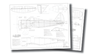
Order Plans from AMA Plans Service
Image
Image
DOWNLOAD FREE NATE PLANS!
Full-size plansDocument
Document
DOWNLOAD FREE NATE TISSUE PLANS!
Tissue plansDocument
Document
Document
Document
Document
Document
Document
Document
Document
Document
DOWNLOAD FREE INFIELD ENGINEERING BREWSTER F2A BUFFALO PLANS!
Full-size plansDocument
Document
Document
Document
Wing Framework
Start the wing construction by pinning the lower main spar and the rear spar to the building board. Use straight 1/16 × 3/32-inch strips of hard balsa or basswood for the main spars. I use balsa, but if you are more concerned about rough landings than weight, basswood is a good choice. Next, glue ribs W2 through W8 into place. Each of these ribs stands perpendicular to the board. Use the dihedral gauge from the plans to set the angle of root rib W1 while gluing it into place. Lock the ribs into position with the upper main spar. Add the 1/16-inch balsa shear webs (parts S1 through S7) to complete the main spar assembly. Attach the trailing edge (TE) to the back of the ribs. Fasten a straight 3/32-inch square balsa or basswood strip to the front for the leading edge (LE). Stack two wingtip (WT1) parts then glue them to the outside of rib W8. Complete the wingtip by joining ribs W7 and W8 with part WT2. Finish the wing framework by installing the aileron parts in numerical order, but don’t glue part A1 to A2. The parting line for the aileron is between these two parts. Give the framework a light sanding to remove any high spots.Sheeting the Wing
The upper surface of the wing between the LE and the main spar is sheeted with 1/32-inch balsa. The center section, including all of the upper and lower surfaces between ribs W1 and W2, is also sheeted to give the wing strength where it connects to the fuselage. I like to attach the upper sheeting in one piece while the wing frame is pinned to the board. This ensures that the resulting assembly will be true. This is a good time to add washout by shimming the TE of rib W8 up by 1/8 inch. Carefully trim the upper sheeting so that the back edge sits on top of the main spar and the shear webs. The front edge should just reach the LE. After the fit is good, dampen the outside of the sheet and glue it in place. Let it dry completely before unpinning it and it should hold its shape nicely. Add the lower center section sheeting and the framework is finished.Controls
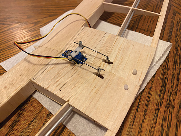
The builder has the choice to install one servo for each aileron or to use a single servo to drive torque rods to both ailerons. The first option is simpler to rig, but when the torque rods are done well, they are completely hidden. If you go with torque rods, it’s easier to install them before the wing halves are joined. On the prototype, 1/16-diameter music wire was used for the bellcranks at the ends of each torque rod. A 1/8-inch diameter aluminum tube was used for the main shaft. A little 3/32-inch diameter aluminum tube was used to fill the gap between the wire and the larger main shaft. The result was a torque rod with sufficiently rigid arms and main shaft but with a modest weight.Joining the Wing Halves
A plywood dihedral brace is included. After sanding each wing root completely flat, install the brace up through the bottom of the wing. Mount the brace behind the main spars the same as the shear webs in the other bays. After the brace has been successfully test-fitted, epoxy the wing halves together then epoxy the brace into position. Add a bit of 1/8-inch dowel for a wing pin at the wing root LE.Belly Hatch
Now it’s time to fit the wing to the fuselage. Start by cutting out the airfoil that is marked on the wing saddles. Carefully cut through keel K4 and the stringers that are between fuselage formers F2 and F2H and F5H and F5B. Coax the belly hatch free from the fuselage. Mate the wing to the fuselage by inserting the wing pin into the reinforced hole in fuselage former F2. When the TE is pressed against the wing-bolt boss, the bottoms of fuselage formers F3 and F4 should touch the top of the wing sheeting. Lightly sand the wing saddles if needed to get the right fit. Now fasten the wing to the fuselage with two nylon 10-32 screws and nuts. After the wing is seated in the fuselage, fit the belly hatch in a similar fashion. F3H and F4H should rest against the bottom sheeting. The gap between the wing saddle and the wing should be small and even, and the hatch should fit flush with the fuselage. Use rare-earth magnets to hold the belly hatch in place between battery swaps.Image

Image

Image

Image

Image
Image

Controls
For the prototype, a servo tray was made from scrap balsa and fitted between formers F3 and F4. Two 5-gram servos and .035-inch control rods were installed to drive the rudder and elevators. Two motor options were fitted. The first was a 24-gram Blue Wonder-type motor. These were popular a few years ago but have become relatively scarce. That led to the evaluation of a second motor. A Turnigy 2822-1275 Kv brushless motor and its larger 15-amp ESC weighed 20 grams more, but this combination is a drop-in replacement for the 24-gram motor and produced 50% more power.Finishing
The prototype Buffalo was covered in Polyspan fabric. Mod Podge was used as a heat-activated adhesive. A little was brushed onto the framework, allowed to tack, and then the Polyspan was ironed into place. After trimming and shrinking the Polyspan, waterbased polyurethane was used as dope. Five coats, thinned with 70% water, were brushed on. After the dope was dry, another session with the sealing iron followed. The four colors of the paint scheme were all Behr interior latex colors. The mixture I used was 40% paint, 30% water, 30% isopropyl alcohol, plus a splash of ammonia. The addition of alcohol sped up the drying, while the ammonia helped the paint wet a little better. Even so, extremely light coats were required to avoid runs. Judicious use of a heat gun helped a lot. Several plastic parts are required to complete the project. A vacuum-formed canopy comes with the kit, or one can be ordered separately from Park Flyer Plastics. Several other parts are available as 3D-printable files. These can be downloaded from Thingiverse. Search for Infield Engineering Buffalo. There are files for the dummy wheels, a dummy motor, and a two-piece spinner.Flight Report
The prototype Buffalo weighed 10.9 ounces with all of the paint and details, plus the 24-gram motor and a 500 mAh LiPo battery. This is slightly more than Derek’s Nate, but I have two excuses for that. First, the Buffalo has a larger power system than the Nate. Second, historical accuracy required that the U.S. Navy fighter be a bit "portly" compared with its nimbler Japanese counterpart. In any event, this Buffalo flies like a dream. For all of my flights so far, I’ve hand-launched it myself because my wingman chickened out. That hasn’t been a problem because the Buffalo simply lifts off with determination. Loops are appropriately large, and any scale maneuver is readily done.Image

Image

Image

Image

Image


Comments
error on plans
plans pdf are for ki27 nate not brewster buffalo
pit
Add new comment