Golden Age racing via flat foam
By Larry Kruse Photos by Harold Anderson and Larry Kruse
As seen in the March 2023 issue of Model Aviation.
Editor’s note: On August 2, 2021, AMA lost one of its frequent contributors to Park Pilot and Model Aviation magazines, Larry Kruse. We were recently asked about publishing a at-foam electric in Model Aviation and immediately thought about Larry and his May Bee. It was originally published in Park Pilot magazine, and we are happy to share it with you in this issue of Model Aviation.
My local club has become eclectic during the past few years, with interests ranging from Giant Scale to large and small glow-engine models, EDF jets, electric-powered airplanes of all sizes, and indoor airplanes flown once a month.
Recently, at-foam models have made a resurgence with our members in the form of some easy-to-build, great-flying, and imaginative aircraft developed by indoor ier and former FAI Aerobatics competitor, Joe Gross.
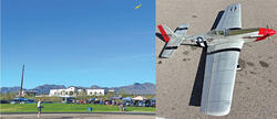
The May Bee has charisma in the air thanks to its Gee Bee heritage. Color separations and markings make it highly visible in the air. It has gentle landing characteristics.
Joe has a range of designs, all constructed from Dollar Tree foam board, and he specializes in providing completely built airplanes at reasonable prices. Consequently, nearly all of our club’s indoor and park years have at least one "Joe Plane."
Joe’s flat foamies tend to have generous, squared-off surfaces and are not intended to be scalelike. I began wondering what could be done with an airplane by using his parameters and giving it sort of a "cartoon-scale" flavor. As I thought about a full-scale airplane with a stubby-chubby prof ile and planform, the Granville Brothers’ Gee Bee came to mind.
DISCOVER MORE CONTENT!
Free Plans for the May Bee can be downloaded from the Park Pilot website at www.TheParkPilot.org/build-may-bee.
I began sketching and cutting foam and, in roughly a week, I had something different enough to take to a club meeting for show-and-tell. When several of our members saw it, they said, "Oh, a Gee Bee!" I responded, "Well I wouldn’t go that far. It’s more like a May Bee since it hasn’t flown yet." Odd how names come about, isn’t it?
The May Bee has been tweaked, modified slightly, and flown extensively, so I’m confident it can provide a quickly built, at foamie for your hangar that can be flown outdoors or indoors, with only small trim adjustments.
Construction Sequence
Using them sequentially, in sort of a cookbook fashion, will serve as a checklist of your progress as you move toward the completion of your airplane. The few pieces that comprise the model can be cut out quickly by using the full-size templates that are available as a free download on the Park Pilot website, listed in "Sources." I have found it most useful to back each template with light poster board. Any type of rubber cement or spray adhesive, such as 3M 77 or Elmer’s Sprayment, can be used to attach the templates to the poster board. Scissors or a hobby knife can be used to cut out the patterns.
The two major parts are the front wing piece and the rear stabilizer piece, epoxied together at the V-shaped notch shown.
The airplane parts are few in number and are primarily cut from Dollar Tree foam guided by full-size templates.
Notice that two of the larger pieces are half patterns and should be positioned carefully on the foam board, with the straight edge of the pattern used as a centerline for flipping the pattern over and tracing the opposite side. Tracing around each pattern should be done with a soft lead pencil so that any stray marks can be carefully erased. A ball-point pen doesn’t offer that latitude.
A #11 hobby knife blade works well for cutting out the pieces. Try to hold the knife as vertically as possible. If you happen to cut an edge that ends up slightly slanted, it can be squared up with a T-bar sander faced with medium-grade sandpaper. Foam board tends to dull cutting edges quickly, so instead of tearing the backing paper, change the #11 blade as needed.
After the parts are cut, it is easier to paint the scallops on the top and bottom of the wing halves and the color separations of the fuselage pieces before assembly. Because the airplane is constructed with the paper backing of the foam sheets intact, choose a painting method that will not lift or curl the paper by getting it too wet. Alternately, a coat of oil-based Minwax can also be brushed on and wiped of with a lint-free rag to seal the paper backing before painting. Be careful to keep it away from the joint lines because hot glue will not stick to a surface with Minwax.
I used low-tack artist’s frisket film as a mask for the scallops and color separation lines, and air-brushed the red color using multiple light coats of thinned acrylic enamel. When properly applied, air-brushed paint goes on essentially dry. Patience is the only thing you will need as you alternate between the fuselage and the wing to get the paint to the point of opacity and not dampen the paper backing on the foam board.
Wing scallop lines and color separation lines are marked on the templates for your convenience. Be sure you totally mask out all areas that shouldn’t be painted to eliminate accidental overspray. The painted portions can also be done with rattle can paints, such as Testors or another commercial foam-safe paint, if airbrushing is not your thing. Just be sure to apply several light coats to avoid lifting the foam board’s paper backing unless you’ve used Minwax to seal it from any moisture.
After the paint has dried, use 5-minute epoxy to join the front wing piece and the rear stabilizer piece, carefully wiping off any excess epoxy that seeps out. Keep the two pieces flat until the epoxy cures. When it has cured, draw a centerline on the top and bottom of the joined pieces to guide you in hot-gluing the top and bottom fuselage parts in place. You will need to work quickly before the hot glue sets up.
Experiment with some scraps of foam to make a right-angle joint so that you can arrive at a comfort level before the real gluing process begins.
Using the centerline referenced in the previous step, run a bead of hot glue down the line and put the bottom of the fuselage in place, holding it at 90° until the glue cures. Run a bead of glue down each side of the joint to add strength. Flip the wing/stabilizer over and raise it up enough so that it can rest flat with the bottom of the fuselage hanging down and not touching anything.
A 3-inch section of a bamboo barbecue skewer provides the connecting joint between the two elevator halves. The pieces should be dryfitted together before the epoxy is applied to the skewer and the two foam elevator pieces.
I used piles of books under each wing to give the appropriate clearance. Repeat the gluing operation for the fuselage top, running a bead of hot glue down the marked centerline, and then along each side of the joint after the base glue cures. Be careful to hold the piece at 90° to the wing/stabilizer platform until it is locked in place.
The addition of the 1/32 round motor mount will complete the basic structure. Run glue down and across the cruciform shape of the front and carefully position the motor mount, holding it firmly in place until the glue cures. For additional strength, add generous glue fillets to all of the surfaces at the back of the motor mount/fuselage joint.
The sub-assemblies are next. Because they are all control surfaces, sand a 45° chisel shape with the angle facing down on each leading edge (LE) surface of the elevators and ailerons. Be sure to make a right and a left side for both! Sand an equivalent chisel-shaped angle to the rudder’s LE, using whichever side you choose. A T-bar sander works well for this operation and keeps all LE surfaces straight while cutting the required angle for movement.
The elevators can now be notched as shown on the elevator template to accept the 3-inch bamboo barbecue skewer that will provide a secure connection between the two pieces. Poke a few small, shallow holes in the foam in the notch to provide an additional gluing surface. Test-ft the assembly against the stabilizer’s trailing edge (TE) to make sure everything fits, and trim, if necessary, to ensure that the length matches the stabilizer length.
Epoxy the pieces together on top of waxed paper using 15-minute epoxy. Keep everything flat and square to the stabilizer’s TE as the epoxy sets up. After the joints have cured, take a small amount of epoxy and go over them again to make sure glue has reached all of the surfaces.
Hinging the surfaces comes next. Several hinging methods can be used on flat-foam airplanes using various kinds of tape. The one that I like is the quickest and simplest, involving two steps and 1-inch Du-Bro Electric Flyer Hinge Tape.
Place the two surfaces to be joined butted together top side up. The chisel shape of the moveable surface should be pointing down. Cut a length of the hinge tape approximately 1 inch shorter than the length of the surfaces to be joined. Lightly and carefully place it lengthwise over the two surfaces, keeping them touching along their seam. Press the tape down firmly after it’s located to your satisfaction.
Now cut two 2-1/2-inch pieces of tape and set them off to the side. Fold the two surfaces you just joined back over each other, keeping the edges even, and then apply the short pieces of tape perpendicular to the joint. Space them out so that they support the surfaces equally and rub them into place, particularly over the bare foam of the edges.
Flatten out the surfaces and flex them a few times to make sure that the joint moves easily. The rudder uses the same technique as the elevators and ailerons, but the tape should be placed in two locations—one above and the other below the elevator notch on the rudder.
These views of the finished airplane show its generous surface and control areas, as well as an unusual platform in the air.
The pushrod locations cross over each other but have plenty of clearance. All of the electronics and controls are located on the bottom side of the fuselage for a cleaner look in the air and on the ground.
Radio and Power Installation
Placing the electronics on this model—particularly the three servos—was of great concern in order to meet the projected center of gravity (CG) of 33% of the wing chord located 6-1/2 inches back from the front of the motor mount. Although there was some wiggle room to adjust the 2S 500 mAh battery fore or after, the CG location, marked on the upper fuselage template, was the target in order to avoid needing to add any additional weight to the nose.
As you arrive at the locations for your electronics, you might want to experiment with several placement arrangements before committing to any of them. Simply lay the components out on the horizontal surface area and test-balance the airplane each time.
I used three 9-gram TowerPro MG90S metal-gear servos. As the photos show, two servos were located in front of the CG and one was directly on the mark. The 10-amp ESC and the Tactic TR624 receiver were crowded as far forward as possible and held in place with double-sided tape and hook-and-loop material, respectively. A strip of hook-and-loop material for the battery was mounted on the opposite side of the fuselage, as close to the back of the motor mount as the glue fillets would allow.
The left underside of the fuselage shows the battery mount, the elevator servo, and the aileron servo that is center-mounted in a hole cut in the lower fuselage. The aileron servo arms extend on both sides of the fuselage.
The TH 2006-17T 1,500 Kv motor and 7 × 5 propeller assembly were screwed onto the motor mount with screws long enough to penetrate the foam. Small holes were cut to allow the wire from the ESC to reach the battery and the servo lead wires to connect to the receiver.
Control Surfaces
Because of the position of the servos, some long pushrod runs were necessary. I used .047 music wire for all of the pushrods with Du-Bro Micro 2 Control Horns mounted on the control surfaces using foamsafe CA adhesive. In order to keep the elevator and rudder pushrods from flexing, I used two micro control horns as standoffs for each pushrod and threaded the pushrods through them before connecting everything, as the photos show.
The best technique for connecting the servos, pushrods, and control horns is to mark the location of the horns and drill holes to mount them, but don’t glue them in place until each pushrod is formed to length with a built-in adjustment kink for minor tweaking. I recommend a dry run. Because the aileron servo is embedded in a cutout in the lower fuselage with a control arm located on both sides of the fuselage, the servo control arm must be centered before the servo is hot-glued in place.
After the aileron servo is firmly mounted, the prefitted pushrods will need to be connected to each side of the servo arm and their respective control horns before the horns are glued in place. Z-bends are used to connect both ends of each pushrod, which imposes some limitations on how and when all connections must be made.
This shows one of four micro control horns used as standoffs for the rudder and elevator pushrods. The standoffs need to be threaded onto the pushrods before the rods are attached to the servos and control horns. The micro control horns can be sunk into the foam board at any location and glued in place using foam-safe CA glue.
Finishing the May Bee
After the electronics and controls are mounted and complete, all that is lacking is giving the airplane some character with Gee Bee markings gleaned from the internet and printed on bond paper. Everything on the airplane was simply cut out with a sharp #11 blade and attached to the surfaces using a glue stick.
The May Bee lettering on the rudder was printed from the stock font styles in Microsoft Word. The canopy was cut from MonoKote trim sheet (both left and right sides are required) and stuck to the fuselage sides.
Because the model is a belly-lander, I added some clear packing tape to the front of the fuselage using a 1-inch strip laid along the bottom of the fuselage, and then notched and wrapped it to protect against damage.
The May Bee in Flight
At this point, the work was completed and the fun began. Using the CG location shown, I moved the battery slightly forward to achieve the required balance. I set my transmitter for low rates and reduced all throws to 70% with 25% exponential. High rates were left at 100% with 25% exponential to soften the controls.
The first test fight was done right at sundown one calm evening in my front yard. With an underhand launch at roughly 50% power and about four clicks of up-elevator, the airplane skimmed along at a 4-foot altitude and made a complete circle, landing just in front of me. I knew it was good to go!
The full maiden fight that followed the next day proved that the model was both aerobatic and stable. Maintaining four clicks of up-elevator for launch (which can be trimmed out after the airplane reaches altitude), it is easy to fly in all modes. It can perform nearly any maneuver you can think of and slows to a hover for landing.
It is unusual and sort of funky looking in the air. Although it’s not scalelike in any way, it has a certain charisma about it that attracts attention.
I would be remiss if I didn’t thank my fellow club member, Harold Anderson, for flying the airplane so that I could get the necessary flight photos, and Joe for his formulaic approach to the flat, foamie design that inspired the May Bee.
At a Glance
Specifications
Model type: Flat-foam park flyer
Skill level: Intermediate
Wingspan: 30 inches
Length: 24.75 inches
Wing area: 240 sq. in.
Weight: 7.5 ounces (without battery)
Wing loading: 4.5 ounces per square foot
Power: 2206 1,500 Kv outrunner
Propeller: 7 × 5 APC
Battery: 2S 500 mAh LiPo
Radio equipment: Tactic TTX650 transmitter; Tactic TR624 receiver
Flight duration: 5 to 7 minutes, depending on throttle management
SOURCES:


Comments
Add new comment