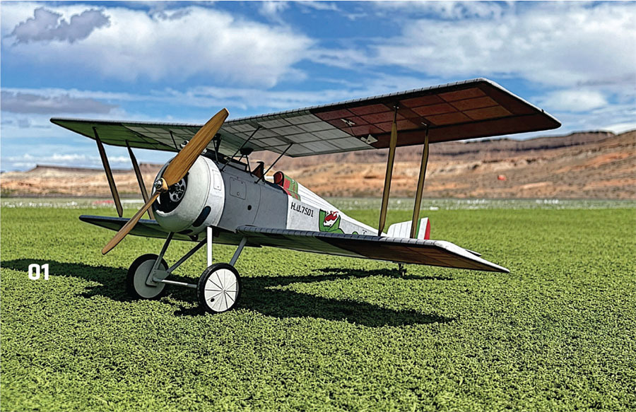
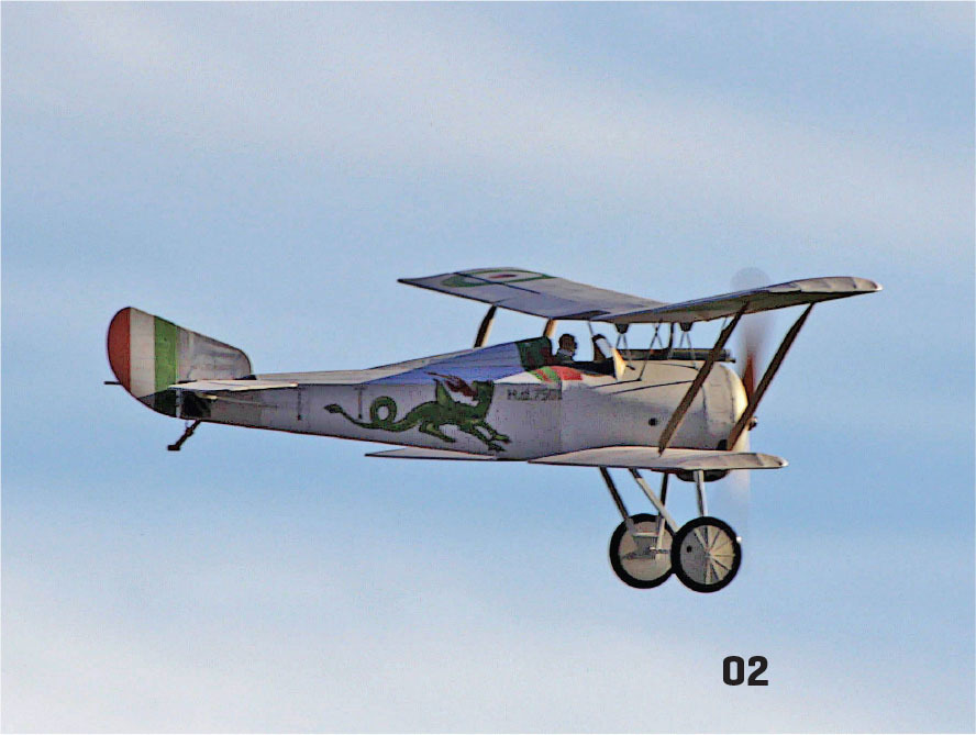
In 2018 and again in 2021, Paul Kohlmann and I collaborated to design models of aircraft that opposed each other during World War II. For our third installment of "Fighter Face-Off," we decided this time to design and build aircraft from World War I.
In trying to keep with our "lesser-modeled aircraft" theme, it was more of a challenge than we initially thought it would be—even today, WW I aircraft still have a significant cultural relevance. In the Peanutscartoons, Snoopy famously flew a Sopwith Camel, and even the Red Baron and his red Fokker triplane have a pizza brand named after them. After some aircraft searching and sleuthing, Paul chose the LFG Roland D.VI and I chose the Hanriot HD-1.
The HD-1 was a French design by the Hanriot company that entered service in 1916. Looking like a cross between a Sopwith 1-1/2 Strutter or Pup and a Nieuport 17 with comparable performance, it was ultimately rejected for use by the French Aéronautique Militaire; however, it found a home with both the Belgian and Italian forces, the latter of which produced it under license. Both air services had great success with fighter vs. fighter action and balloon busting. Postwar, the French and U.S. Navy experimented with a float version of the Hanriot.
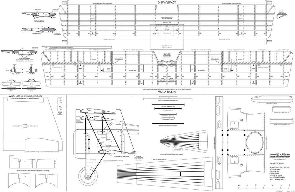
The HD-1 model has a wingspan of 30 inches and is powered with a 24-gram, 1,300 to 1,700 Kv motor spinning an 8- or 9-inch propeller and a 450 to 500 mAh 2S LiPo battery pack. Construction is mostly from 3/32-inch and 1/4-inch balsa and 1/16-inch plywood. The model uses 1.5 mm carbon-fiber rods for the wing and landing gear struts.
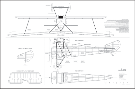
The full-sized plans and parts templates are available on the Model Aviationwebsite at ModelAviation.com. Printed tissue templates and pilot details, as well as construction and covering notes, are also available for download. Those who want to dive right in and not cut your own parts can purchase a short kit from Manzano Laser Works. Rabid Models carries wheels and rims that are designed specifically for the model.

Construction
Construction began with the tail feathers. You can see the Sopwith and Nieuport influences in the fullsized design. The vertical and horizontal stabilizers are built up to save weight, have several parts connected with 3/32-inch stringers, and are hinged with cut-down CA hinges.
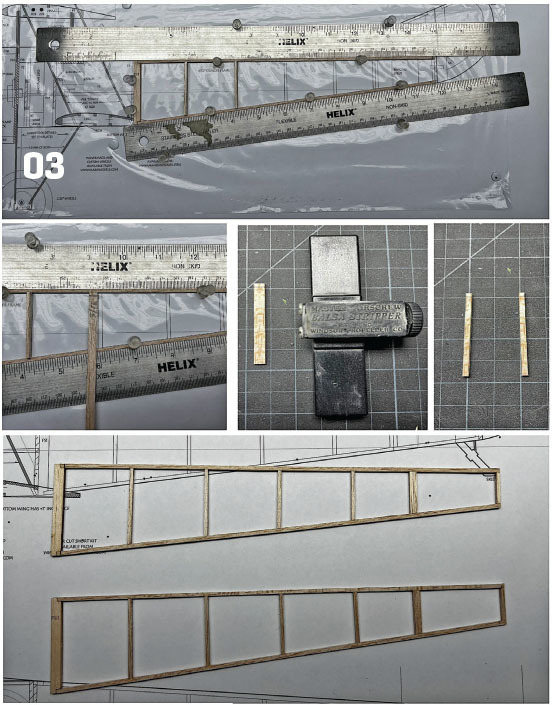
The fuselage is built in two main sections: stringers in the rear and balsa/plywood parts in the forward. The rear section is mostly built from 3/32-inch stringers. The left and right sections are built over the plans— one right on top of the other to ensure that they are as close as possible.
For the vertical/horizontal stringers, I stripped a 3/16-x 3/32-inch plank. Once it was marked for the correct height per the plans, it was trimmed then split into two, making two identical stringers for each half. With the left and right halves framed, the same process was used to make the top and bottom cross stringers.
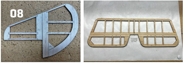
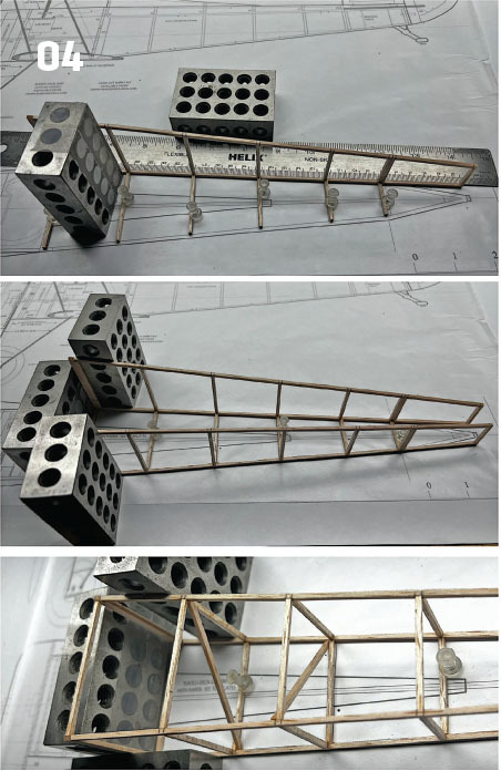
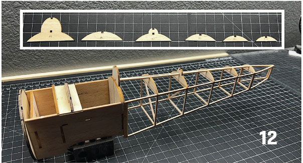
The fuselage halves and top cross stringers were pinned upside down over the Top View plans. Machinist 1-2-3 milling blocks were used to ensure that the framing was true. Once the two sides were glued to the top cross pieces, the bottoms were added, along with a couple of cross-diagonal stringers for rigidity.
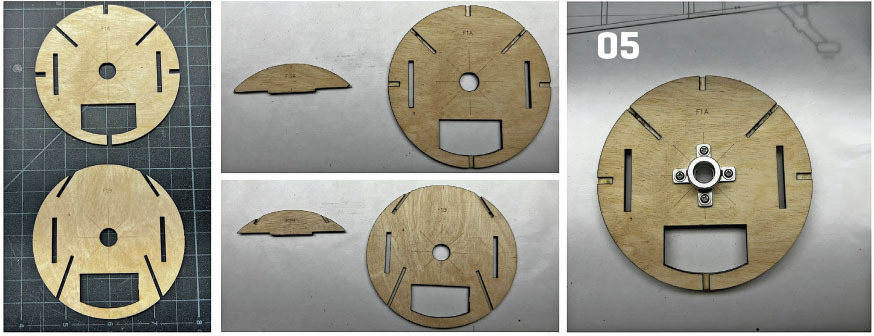
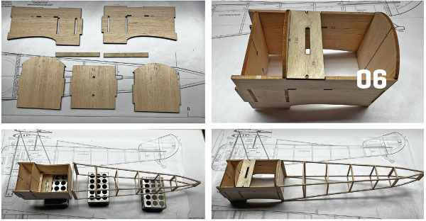
The forward section is made from 3/32-inch balsa and 1/16-inch regular plywood. The firewall (F1A/F1B) is made from two parts that have been glued together. Next, magnets were added to F2 before the forward formers were glued to the fuselage sides (FS). The servo rails (SRs) that are made from 1/16-inch plywood were then added, along with the plate for the F3A/ F3B assembly. Because F3 and F4 have a curved section above the top of FS, the forward fuselage sections were positioned upside down over 1-2-3 blocks before the two sections were glued together.
The motor mount was added to the forward face of F1A; the 1/32- to 1/16-inch shim was also added at this time to achieve the 2° to 3° downthrust. The F1 assembly was then glued to the forward section of the FSs.
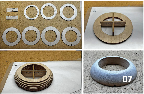
The cowling is made from seven rings (CR1 to CR7) of 3/32-inch balsa. The rings were stacked/glued before being shaped with a sanding block/paper per the plans outline. The cowling was coated with PVA glue and sanded a couple of times to seal the balsa. The four CR8s were added to the back of the cowling into the notches in CR7. These were then glued into the notches in F1A. The six top formers (F5 to F10) were added in place over the rear fuselage section, along with the lower center stringer through the notches in F5 and F7.
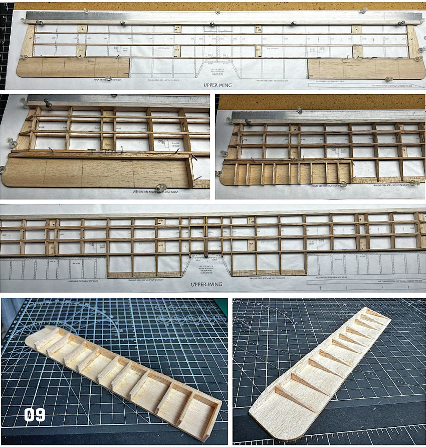
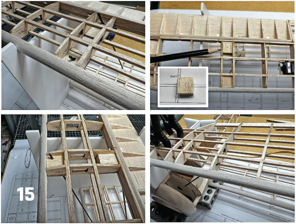
The wing halves were constructed next, starting with the upper wing. The leading edge (LE) blank was cut from 1/4-inch medium balsa, using the forward edge of the ribs to set the height of the blank. The trailing edge (TE) was cut from 3/32 × 3/8-inch balsa planks. The aileron LEs (ALE) were made from either two laminations of 3/32-inch balsa or one of 1/4-inch balsa using the template on the plans. Only the upper wing has dihedral, but it is initially built flat and the dihedral added later.
The LE, TE, ailerons, wingtips, and 1/16-inch plywood strut mounting plates were set/pinned in place over the plans. The bottom 3/32-inch stringers were then added, with the parts glued together.
Next, the ribs were added; note the changes in rib numbers around the strut mounting plates. Rib UW1A that is farthest out toward the tip was added in place before the dihedral angle guides (DAG) forward and rear were glued in place; the inner UW1A was set in place against the DAG so that it tilts toward the wingtip. The ALEs were added next, along with the upper stringers and the aileron servo mounting plate.
The aileron ribs are made from 3/32-inch scrap. The aileron was removed from the building board, and the ribs were sanded to shape. Masking tape was added over the tops of the ribs while the LE was shaped—the short kit/plans also have LE guides to assist with shaping.
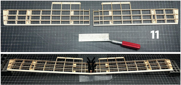
The overall wing frame was sanded before being cut in half, and the sides of the UW1As were sanded flush. The panels were elevated 1 inch at the tips, and Titebond was used to glue the two panels together. The space between the upper/lower stringers in the aileron bay was infilled with scrap. The aileron LE was rounded before cutting the slots for CA hinges.
Two 2.5-gram servos were tested with a horn attached so that it was oriented 90° to the side of the servo. Once they were tested, and with the power off, the horn was gently rotated to be in line with the servo side. The servo was then glued to the plate per the plans, and the wire was fed through the holes in the ribs. The wing’s center section TEs were made from scrap 3/32-inch balsa and contoured per the plans. The lower wing is similar in construction to the upper wing.
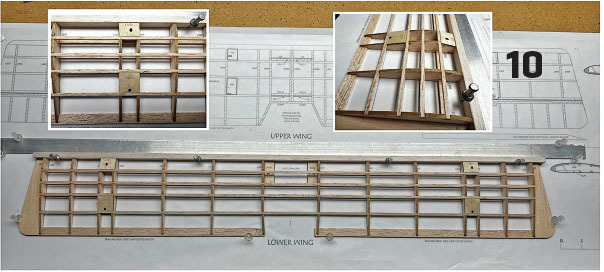
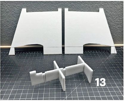
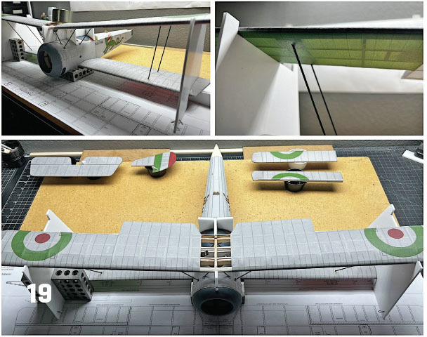
With the main construction completed, the next step was to set up the wing struts. This was aided by several jigs (templates on the plans) that can be made from 3/16- to 1/4-inch foam board or cardboard. Care needs to be taken to ensure that the outer jigs are identical.
The center jig parts were glued together. The 1.5 mm carbon-fiber rods were cut slightly longer to size per the plans. The fuselage/lower wing alignment can be done directly over the Lower Wing plans. Two 1-2-3 blocks were set so that their forward face was even with the rear of F1A/F1B (see the dashed lines on the Lower Wing plans). The lower wing was then set into the fuselage saddle and the model assembly was set on top of the blocks.
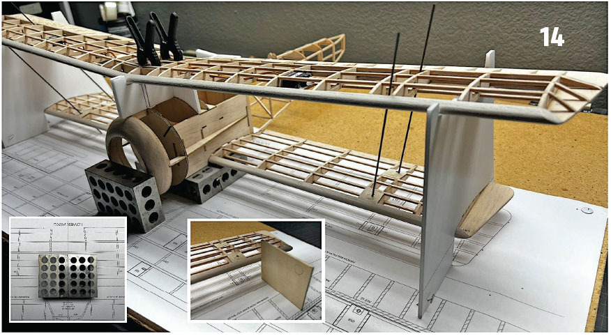
The outer jigs were pinned in place over the outermost rib (dashed lines); make sure that they are 90° to the building board. The center jig was taped/pinned in place on the fuselage per the plans. The upper wing was then set onto the jigs before it was secured with pins or clamps. The four outer struts were slid through the holes of both the upper and lower strut mounting plates. As a reminder, be sure to carefully and properly remove any dust or splinters when you are working with carbon fiber.
Each end of the outer struts was sharpened (like a pencil but with a sanding block instead). These were reinserted into the outer plates so that the tip was just below the surface of the upper wing. The area above the upper strut mounting plates (OSF-R/OSF-L and OSR-R/OSR-L) was infilled with scrap 1/4-inch balsa. The struts were then slowly turned while being pushed up through the holes in the upper strut mounting plates. The struts were extended through/above the top of the upper wing so that the bottom end was above the plate on the lower wing.
The same process of adding 1/4-inch balsa under the lower strut mounting plates (LSMF-R/LSMF-L and LSMR-R/LSMR-L) was used on the lower wing, and then the strut was slid into the balsa. The struts were not glued in place—they will all be glued after covering.
A similar process was used on the mid-struts. The carbon-fiber rod was cut per the plans template, with one end sharpened and slid partially into the slots in F1A/F3A, then pushed up through the holes in MSF/MSR into the rib. The lower section was then seated into F1A/F3A.
The CSR assemblies were previously built and slotted into the upper wing. The inner struts were cut and inserted into the slots in F1B/F3B, and then the upper wing was elevated slightly so that the top ends of the inner struts could slide into the V slots in the CSR assemblies. The upper wing was then reseated onto the struts and the alignment jigs for final adjusting and disassembly. Balsa blocks were added on top of the RGMs (landing gear mounting plates) on the lower wing.
Covering
While the model can be covered with lightweight iron-on film, there are printed tissue templates in an Italian livery that are available for download on the Model Aviationwebsite. The prototype is covered with a combination of paper and printed Free Flight tissue. Some of the templates have the tissue permanently attached to paper for color continuity.
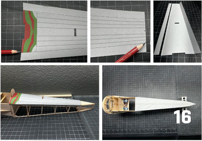
The vertical and horizontal stabilizers were covered first; the rudder has a nice flash of color that represents the Italian flag. The turtledeck was made from a paper/cardstock template (the tissue was permanently attached to a cardstock sheet by using extra spray adhesive on the cardstock before attaching it to the tissue). The sides were intentionally oversized, which allowed the template to be marked when it was set in place over the model and trimmed so that there was only a 3/32-inch overhang onto the side of the fuselage before it was glued in place with PVA.
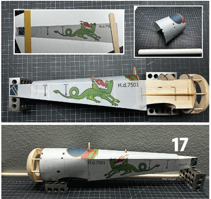
The fuselage bottom was added next. This was printed tissue only. The fuselage side templates are mostly straightforward apart from the mascot’s wing and flames. There is an option to cut along this section and add the details above the fuselage line (a separate template), but the builder can also carefully trim it so that it is a part of the template. It was attached with a glue stick, and the wing/flames section was attached last.
Once the rear fuselage dried, it was shrunk and sealed with Krylon Crystal Clear rattle can acrylic spray. The forward fuselage template was cut out next (the tissue is permanently attached to cardstock). It was pre-rounded using a dowel before test-fitting it to the fuselage. This template covers the top, rounds the sides, and is under some of the lower fuselage. After some final adjusting, it was glued in place with PVA. The main cowling template was added the same way, and the cowling was painted to match.
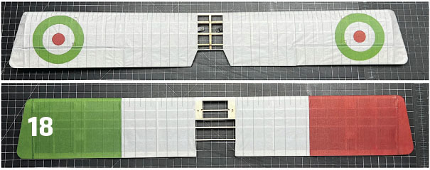
The wing halves were covered in several sections, mostly because of the color differences. The bottom of the lower wing was covered first, starting with the inner panels and moving outward (because of the color overlaps). The top panels were then added to the lower wing.
On the upper wing, the aileron LEs and the aileron bay TEs were covered first. The ailerons were then reinstalled (but not glued) and pinned in place. Starting again with the lower inner panel, each template was added moving outward. When the panels that cover the ailerons were added, glue was applied to the full surface of the aileron and wingtip before adding the template. A popsicle stick was used to gently push in the seam between the bay and the aileron. The center section was left uncovered at this time.
Once the glue had dried, the upper wing was turned over and the pins were removed. The upper templates were added (except for the center section). The wing panels were then shrunk and sealed with Krylon Crystal Clear. The ailerons were cut free by sliding the blade along the rear edge of the aileron bay. The ailerons were removed and the flap/overhang glued down along the aileron LE before they were reinstalled to the wing.
The lower wing was glued to the fuselage and the model was set back in place over the plans (per the previous wing strut setup). The wing jigs were added, as well as all of the struts. After a careful recheck of the alignment, all were glued in place with epoxy.
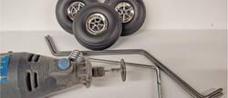
The main strut cover templates were printed on standard paper, cut, folded, and then glued to the carbon-fiber rods. The last stringer (between F5 and F7) was then added. The upper turtledeck (printed cardstock) was glued in place, and the tail feathers were hinged and glued in place with CA. Scrap balsa was added behind F1B to help block in the main landing gear struts. The struts were then inserted into the slots in F1B and the axle bearing (1/8-inch brass tubing) was inserted into the LG parts.
The rear landing gear strut was cut and inserted into the LG parts, and the RGMs were inserted into the lower wing. These were glued in place with epoxy. The Rabid Models wheels really add a nice, scale touch to the model. The lower center templates were added to the wing. On the paper/cardstock sheets, there are templates to make the canopy, pilot, and machine gun.
Electronics
The electronics were installed and connected as far forward as possible, with the ESC and receiver situated per the plans. Several 1/4-ounce weights were needed to balance the model per the plans. The final weight was 8.9 ounces for the completed airframe, and 10.1 ounces ready to fly. That gives it a wing loading of 6.6 ounces per sq. ft.
Flying
The model is a lot of fun to fly! Takeoffs are in just a few feet—the airplane has plenty of power. Loops, stall turns, and Lazy Eights are straightforward. When you come in for a landing, keep the power on; there is a lot of drag on WW I biplanes, so a gradual reduction on final will result in a soft landing.
The Hanriot HD-1 has a lot of character; I recommend giving one a try. It might never be iconic enough for a pizza company to bear its name, but perhaps someday, if interest in the aircraft grows, it could inspire one that makes calzones.
SOURCES:
Rabid Models
"Park Flyer Fun Scale Models-Hariot Hd-1 Fighter Face-Off 3"
RCGroups




Comments
Add new comment