
Written by John Morgan
Build your own park-ready Buffalo
Free plans and build photos
Photos by the author
Featured in the January 2016 issue of Model Aviation.
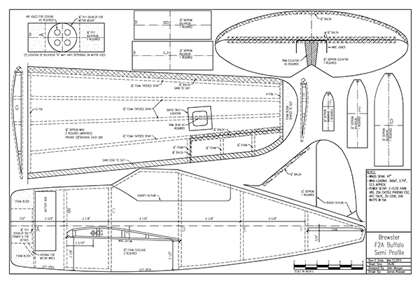
Download Free Plans
Document
Document
Image

Order Plans from AMA Plans Service
Image
Image
Specifications
Model type: Semi-profile foam park flyer Skill level: Intermediate Construction: 1/4-inch or 6mm Depron foam with 1/8-inch plywood motor mount Wingspan: 47 inches Length: 33.5 inches Weight: 34 ounces Motor: RCTimer A3548/6 790 Kv outrunner ESC: HobbyKing 40-amp Battery: Turnigy 3S 2,200 mAh LiPo Propeller: ParkZone Bf-109G three-blade; Du-Bro three-blade, 2-inch diameter spinner Radio system: Turnigy OrangeRx receiver and Turnigy hexTronik HXT900 9-gram servos Flight duration: 5 to 6 minutesBackground
The Brewster F2A Buffalo was an American fighter designed and built by the Brewster Aeronautical Corporation. It was one of the first monoplane fighters with an arrester hook and won a competition against Grumman’s F4F Wildcat in 1939 to become the Navy’s first monoplane fighter. By the time the US entered World War II, the Buffalo had become obsolete because of its ever-increasing weight from various modifications without a corresponding increase in power. The F2A only saw combat with US units once at the Battle of Midway, where it was outclassed by Japan’s extraordinary Mitsubishi Zero. After the Battle of Midway, the Buffalo was retired from combat and reassigned to training units. Several other countries ordered the export version of the Brewster F2A-2 including Britain, Belgium, Netherlands, and Finland. The Finns were the most successful with the Buffalos—flying them against early Soviet aircraft with excellent results. I have always had an attraction to the Buffalo. There is just something in that tubby, rotund fuselage that pleases my eye. As in most of my scratch-builds, a three-view enlarged on my overhead projector produced the outlines that were needed to develop the plans. It is a simple and fast build that ends with a lightweight and great-flying model. The model is built mostly from Depron foam, with a small amount of balsa and light plywood thrown in. Let’s get started!Fuselage
Start by using spray adhesive to stick the parts to the Depron sheets, then cut out all of the parts. This speeds up the building process. Glue the 1/8-inch light plywood motor mount to the firewall and predrill the holes to mount the motor.Image
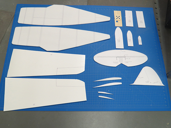
All of the parts are cut out, making a kit.
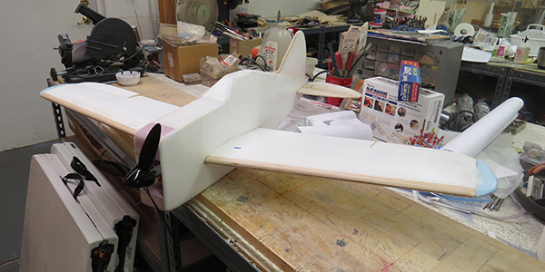
Not shown on the plans are cutouts in the formers for wiring and equipment installation. Place the two fuselage sides together and push holes through the leading edge (LE) and trailing edge (TE) locator points of the wing and stabilizer. This will ensure correct wing/stabilizer incidence later when they are mounted. While the two sides are together, mark former locations on each side. On a flat building board, glue the flat sections of formers A, B, C, and D to one side, leaving the top tapered section for later and making sure that they are perpendicular to the fuselage side. Now align and glue the other side to these formers, making sure that all is square and true. Draw the two fuselage sides together at the rear and glue, again ensuring that they are square. (We don’t want any bananas here.) At this point, install formers E and F. When all of that is dry, pull the tops together using masking tape and glue these tapered sections. Add top and bottom sheeting to complete the basic fuselage. Fill in the foam sections to form the cowl, sand the edges to a round shape, and the cowl is ready for covering.
Wing
Make sure you create a left and right panel. I like to build both at the same time to avoid mistakes. For each panel, pin down the bottom sheeting on the building board and cut tapered washout shims for the TE. These shims are not shown on the plans and should be 1/4-inch tall and tapered to a point roughly 16 inches long. Pin this washout shim under the TE, 1/4-inch tall at the wingtip, to ensure that approximately 3° of washout will be built into the wing panel. Glue the root and tip ribs, plus the LE cap strip to provide the gluing surface for the balsa LE and top sheeting. Add all of the Depron spars that taper from the root to the tip. Stick a pin through the aileron corners to mark their outline so they can be located after the wing panel is closed up with the top sheeting. This will create a reference point for cutting them free later. Build up the ailerons with the Depron and balsa ribs and the balsa spar sections that will be for hinging purposes. Use wood glue to attach the 1/2-inch balsa LE, and the wing is ready for top sheeting. I like to cut an oversized piece of Depron foam and then use Gorilla Glue to adhere it. Gorilla Glue works well because it dries slowly and expands to fill any voids.Image
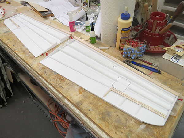
The wing is ready for top sheeting.
Spread the glue on all of the top surfaces and weigh the top sheet down well to hold the sheeting in position until the glue cures. Old issues of Model Aviation distribute the weight well. When dry, remove the panels from the board, shape the LE, and sand the edges. Add foam sections for the wingtips and carve and sand them to shape. Locate the marks outlining the ailerons, cut them free, and prepare them for installation by shaping the LE and making the hinging slots. The wing panels and ailerons are now ready for covering.
Tail Feathers
The tail is as simple as it gets. Cut out and glue in the balsa inserts. Sand both vertical and horizontal stabilizers flush and smooth. Cut off the elevators and install the U wire joiner. Round the edges and make hinging slots for the elevators. They are now ready for covering.Image
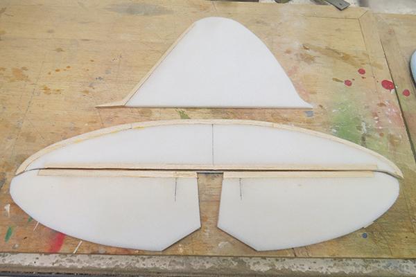
The completed tail feathers with balsa inserts are shown.
Covering
On smaller models, I prefer to use 3/4-ounce fiberglass cloth and Minwax water-based polyurethane. However, the model lends itself to iron-on covering should you choose to go that direction. Fiberglass each surface, trim, and lightly sand when dry with 400-grit sandpaper. I apply two additional coats of polyurethane and sand between coats. At this point, the surfaces should be ready for paint.Final Assembly
On the fuselage sides, take the wing panels and place the LE and TE along the wing datum line formed by the LE and TE holes you marked on the fuselage. Trace the airfoil outline on each side and then cut out these sections, taking the inside part of the former, too, so that the wing will slide through the completed fuselage. Now block up each wing panel for the 21/2-inch dihedral and block sand the proper angle in each panel to ensure a close fit. Join the wing by gluing the two together and give the seam a narrow strip of fiberglass cloth on the top and bottom. While this assembly is drying, cut out the horizontal stabilizer sections on the fuselage sides and check for fit. Trim to suit if necessary. Slide the wing into the fuselage, trimming as required, and make sure it is square and centered to the fuselage. Glue the wing solid. Glue the elevator hinges in the elevators only. Slip that section into the stabilizer slot first and move it to the rear to allow the front stabilizer section to be inserted. After both are in, glue the hinges into the front stabilizer. Square up the complete assembly, being careful to level the wing and measure the distance from the wingtips. When you are satisfied that it is straight, glue in along the seams. Add the vertical stabilizer and you should have a semi-profile Buffalo airframe.Equipment Installation
The prototype used an E-flite Park 480 motor, but I chose an RCTimer A 3548/6 790 Kv motor for this version to give it a more spritely performance. HXT-900 9-gram servos were used for both ailerons and elevator. I installed the elevator servo in the rear of the fuselage to allow a short pushrod. A Turnigy OrangeRx receiver was used and mounted in the central bay under the wing, along with a 40-amp ESC. When proper battery location was established for the correct CG, a light plywood battery box was glued in the forward open bay behind the firewall. A ParkZone Bf-109G three-blade propeller, a Du-Bro 2-inch spinner, and a 3S 2,200 LiPo battery work well with this power system. I added 1/8-inch balsa doublers inside the open bay under the wing, along with a partial light plywood former in the middle of that opening to strengthen the area for hand launching.Image
The completed model with all of its equipment installed.
Details and Finishing
I decided to finish this model as the British export-version B-339E that was flown by No. 242 Squadron Royal Air Force in Malaya in 1941. Only a few details were added, including exhausts and the distinctive exposed wheels along the fuselage sides. The exhausts are simply aluminum tubing painted a rusty exhaust color. The wheels were made by chucking a foam cylinder in my Dremel tool and using sandpaper to shape them. These details were added after the painting was completed. I use common household acrylic latex enamel to paint my models. Thinning it roughly 20% with Windex gives a nice, even flow from the airbrush.Image
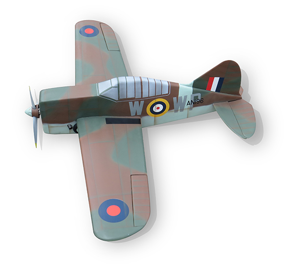
Acrylic latex enamel, thinned approximately 20% with Windex, was sprayed onto the aircraft with an airbrush.
Image
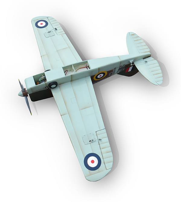
The bottom of the model is painted. The fuselage is open on the bottom to provide easy access to the flight battery.
I started by painting the bottom color first, followed by the upper camouflage surfaces. After the camouflage base colors were on, I went back over the edges to define them, but leave a soft edge. The canopy and rear fuselage stripe were then masked off and sprayed. After a day’s worth of drying, the whole airplane was rubbed down with 1,000-grit sandpaper to remove any overspray and leave a smooth surface for applying decals. Callie Graphics supplied the excellent decals. With the decals applied, it was time to give the model a few simple panel lines. These were applied using a 2B pencil and a plastic straightedge. When they were done, it was back to the airbrush. I wanted to give the panel lines an accent to further define them. Using masking tape along the lines and a light finger on the trigger, a thin layer of paint was spread along the lines—leaving merely a little color. This was done on every line including the simulated rib lines on the control surfaces.
Image
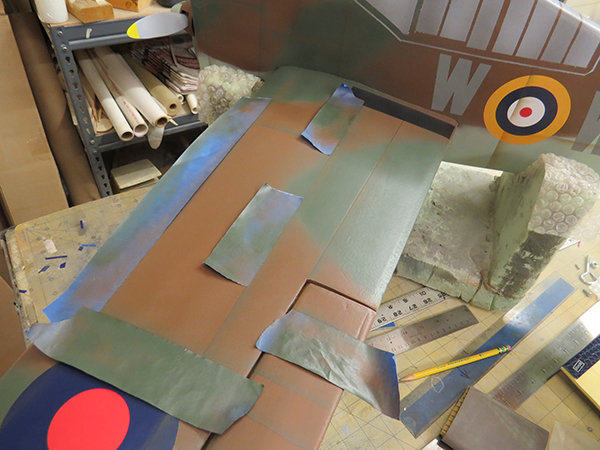
The author used tape along panel lines to apply accent color.
I like to use contrasting colors on the lines. On the green camouflage surfaces, for instance, I use brown to accent. I do the reverse on the brown camouflage with green. Brown was also used on the bottom lines. This gives a nice detail that tends to define the lines well. With the panel lines complete, it was time for a clear protective coat. Krylon makes excellent clear coats and I prefer the satin finish in most cases. The model was given two light coats to protect the finish. Painting the propeller and spinner creates an overall good look to the model. With the painting complete, it was time to recheck the balance and then go flying!


Comments
Thanks for sharing the prints
Thanks for sharing the prints! I want to make this plane, where do you get the depron, blasa and plywood from?
Thanks
Nicolas
You're welcome, Nicolas!
Printing plans...
Hi, with the plan downloaded; what do I need to know to have them printed to the right size?
Thanks
Re: Printing plans...
Printing plans
Hi Gary
what I do:
1 Down load the plan to a USB thumb drive (it is a PDF File). For about $4.00 FedEx Office, or Staples will print a Full Size Print. I have them print 2. one to build on and one to use as templates.
Using KInkos for plan printing
I love building in foam, but one thing I hate is cutting tiled pages then taping them together, only to cut them apart to get park templates. So, I called Kinko's (Now FedEx Packaging and Printing, at least here in MD), and spoke to a rep, and asked if he could print this plan full size. Turns out, no problem at all - they have a huge plotter used for architectural drawings, and this plan printed out perfectly - and only cost $4. So I got 2, to cut part templates. Even better, I just emailed the plans to them, and they printed them out, and had them ready for me when I arrived to pick them up. Can't get easier than that!
Add new comment