
Thicker Control Surfaces and Vortex Generators Explained
Modern modifications that significantly improve any airplane's handling
by Dave Scott ([email protected]) | Illustrations by the author
As seen in the February 2017 issue of Model Aviation
The following article describes the effect that surface friction has upon disrupting the airflow over the surface of the wing, tail, and control surfaces, and then offers some modern solutions to overcome this phenomenon in order to significantly improve handling and control.
Although most pilots are unaware of this phenomenon, they encounter the inherent effects of the control surfaces being surrounded by disturbed/turbulent air every time they fly in the form of erratic, uneven control responses, especially at slower airspeeds. This phenomenon can be particularly troublesome during novice fl ight training because so much of the fl ying is done at slower speeds.
This phenomenon is undesirable when performing aerobatics because the severity of the disrupted airflow varies with changes in airspeed and angle of attack. Airspeed and angle of attack change constantly while performing aerobatics, and the ensuing uneven control responses interfere with a pilot’s ability to predict and positively control his or her maneuvers. This becomes an even greater issue when flying in windy conditions because of the importance of often needing immediate and positive corrections.
Boundary Layer Basics
Surface friction causes the air in contact with the wing, tail, etc., to slow and become turbulent. Away from the surface, the air molecules will be less turbulent until a point is reached where the airflow is smooth. The layer of air from the surface to the point where there is no measurable slowing is known as the “boundary layer.” As the airflow progresses aft, the turbulent boundary layer becomes progressively thicker and more severe (Figure 1). You can see this same phenomenon when wind contacts the surface of a lake and creates ripples that then grow into larger waves.
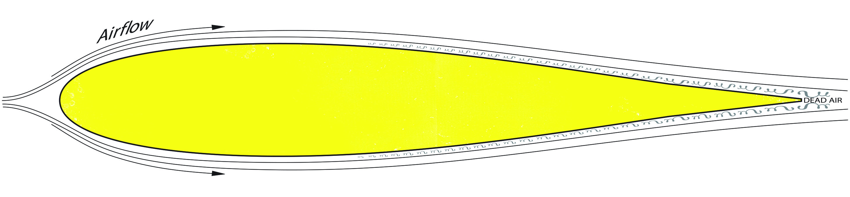
Figure 1: Surface friction causes the air in contact with the wing’s surface to become stagnant and/or turbulent. As the airflow progresses aft, the turbulent boundary layer becomes progressively thicker and more severe.
The turbulent boundary layer produces more drag, but more importantly, it is prone to causing airflow separation leading to an earlier and more severe stall, along with degrading the effectiveness of the control surfaces, especially the ailerons. For example, small control surface deflections within the turbulent boundary layer tend to produce sluggish and/or erratic responses, particularly at slower airspeeds. In order to begin achieving positive control, pilots must apply larger inputs to deflect the surface into smoother air, at which time there is an exponential increase in the rate of response. Traditional beveled leading edge (LE) control surfaces further disrupt the already turbulent airfl ow as a result of the air tripping over the bevel’s sharp corners, and further compound the uneven control response. The most noticeable aspects of flying with conventional beveled control surfaces are difficulties in keeping the wings level—making fine adjustments, with response rates that exponentially speed up and slow down with airspeed changes—thereby interfering with a pilot’s ability to precisely predict the effects that his or her control inputs will have on the airplane. Tradition, ease of manufacture, and the dominance of 3-D designs requiring huge control surface movements, are the reasons that this primitive design continues to be used. It is also because of this design that many manufacturers have to resort to sealing the gaps to try to limit some of the inherent airflow disruption and potential for flutter. Thicker Control Surfaces and Positive (Linear) Control The airflow is smoother slightly away from the surface of the wing or tail. Incorporating slightly thicker control surfaces places the physical surface of the ailerons, elevator, and rudder flush with the smoother airflow, thereby improving stability and control as much as 50%! A round LE applied to a control surface further improves control by providing a smoother contour for the airflow to pass over the surface without becoming turbulent (Figure 3).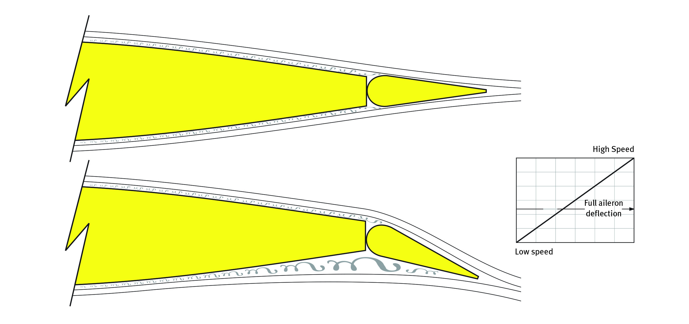
Figure 3: Thicker control surfaces with round LEs achieve a smoother airflow over them and therefore provide greater stability and a more even (linear) control response starting from neutral. They help the airflow remain smooth and attached to the control surfaces when deflected for maximum control authority at all airspeeds.
Image
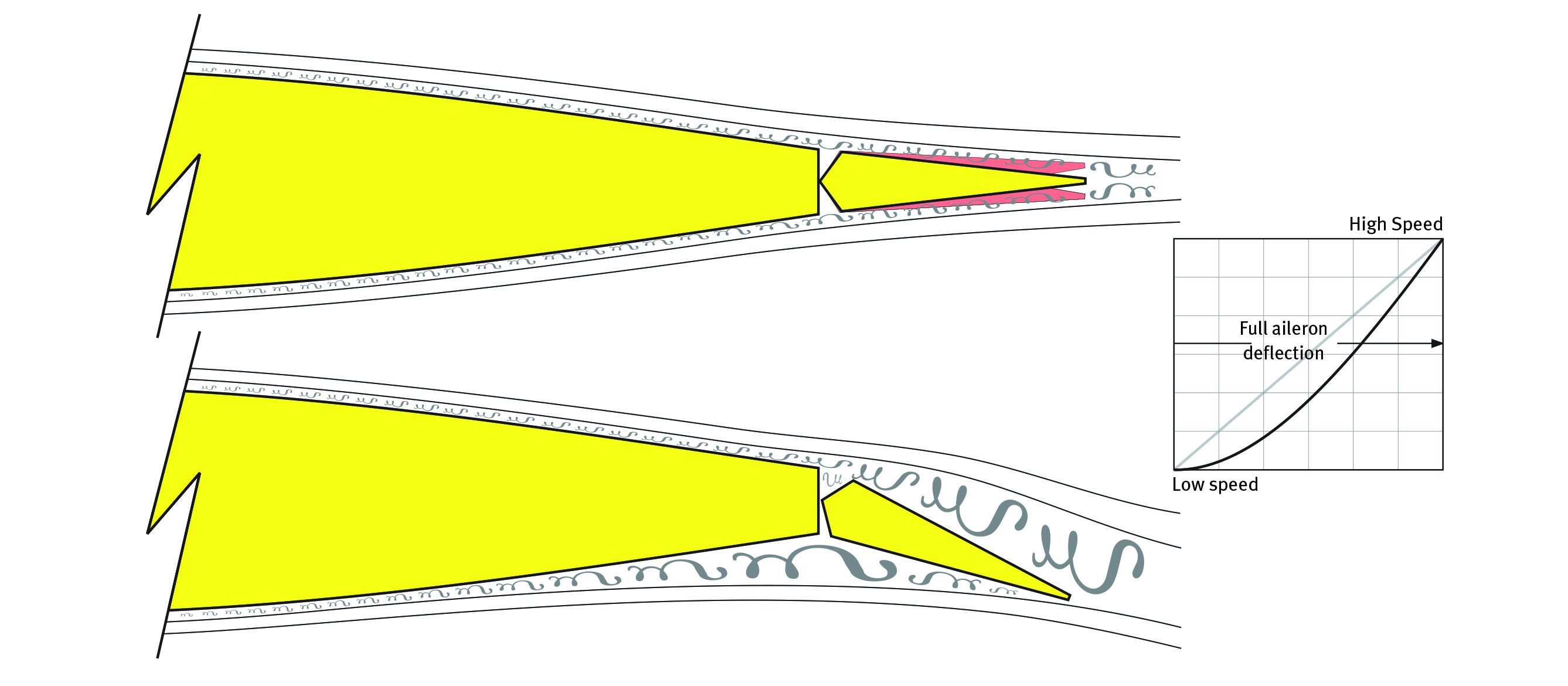
Figure 4 (top): Surface (skin) friction causes a turbulent boundary layer to develop, which surrounds all of the control surfaces. Traditional beveled control surfaces with sharp corners further aggravate the
already turbulent air. The result is uneven control responses and an increased potential for control surface flutter!
Figure 2: Traditional beveled surfaces produce an initial sluggish response and an irregular response rate that impairs a pilot’s ability to predict how the airplane will respond to commands, especially at lower airspeeds.
Thicker control surfaces with round LEs are utilized on nearly every full-scale aerobatic aircraft designed since the 1980s, including every full-scale Extra, Edge, MX, Cap, modern Pitts, and more. The improved control they provide has not only helped these aircraft dominate World Aerobatic Championships and individual competitions, but raised LE surfaces are largely responsible for the expanded control envelopes demonstrated by modern aerobatic aircraft today!
Benefits
Specific benefits of thicker control surfaces with round LEs are:
- Pilots experience a more predictable linear one-to-one correlation between their control inputs/intentions and the response of the airplane, especially when making smaller inputs.
- The minimum controllable airspeed is lowered on all aircraft, expanding their flight envelopes.
- Greater stability in turbulent air and smoother, more positive control responses during aerobatics and when the aircraft is low and slow during landing.
- The potential for flutter is significantly reduced (making sealing the gaps unnecessary).
The drawbacks of thicker control surfaces are the hassle of having to build them yourself, and unless the hinge axis points are recessed into the control surface, the round LE can limit surface travel. Therefore, although 3-D flying would also benefit from thicker surfaces, this design is primarily applicable to Precision Aerobatics and RC Scale, where the surface deflections are not so extreme.
Thicker control surfaces all around would be optimal, but it is the ailerons—control of the wing—that are the most important. To achieve the increased thickness, you can either purchase thicker balsa stock or build up the LE of the provided ailerons with lightweight strips of balsa on one side and re-center the hinges, or add balsa strips to both sides.
Vortex Generators
When it is impractical to install thicker control surfaces on an existing model, vortex generators (VGs) can be used to accomplish the same effect, if not more.
VGs typically consist of small vanes or fi ns positioned near the wing’s LE that energize the boundary layer by creating vortices (tiny tornados) that pull fast-moving air down through the previously discussed stagnant or turbulent boundary layer near the surface. By energizing the airflow, VGs enable the wing to operate at higher angles of attack before stalling, provide gentler stall characteristics, and increase control and stability, especially at lower airspeeds.
VGs are indeed revolutionizing aircraft performance, and thousands of full-scale aircraft have been fitted with them during the last couple of decades to improve short-field performance and low-speed handling, to a degree that is hard to believe until you experience it.
When lowering the stall speed is not important because of the model’s already mild stall characteristics, VGs can be placed directly in front of the ailerons, and/or ahead of the rudder and elevator, to enhance control authority by reattaching and energizing the airfl ow over those surfaces (Figure 5).
Image
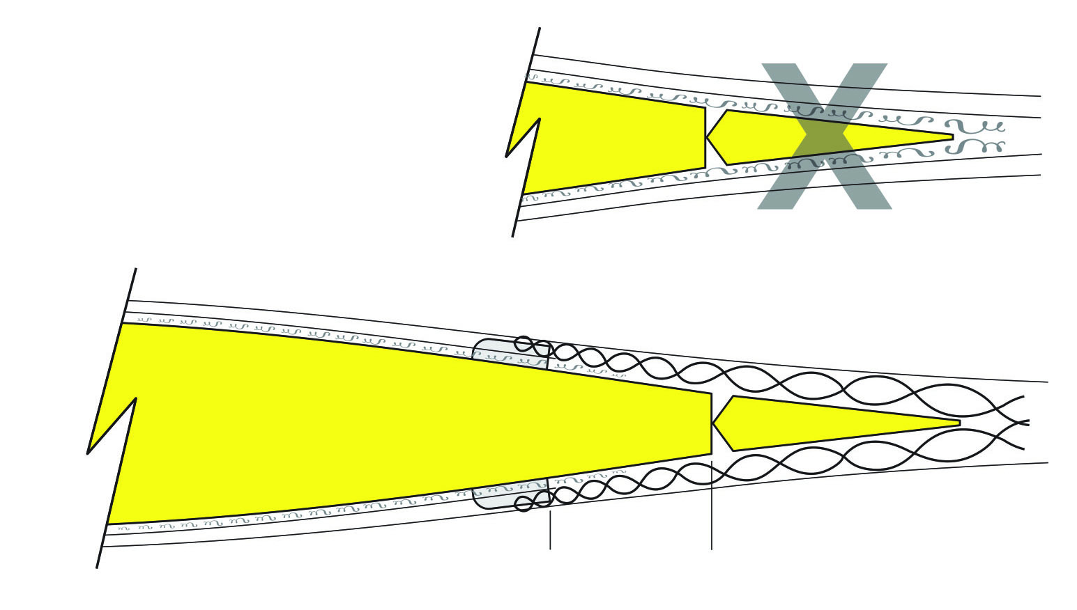
Figure 5: VGs positioned 1 to 3 inches in front of the ailerons on the top and bottom of the wing reenergize the airflow over the ailerons to maximize control authority and generate a linear control response.
1st U.S. R/C Flight School bends its fin VGs from clear plastic windshield material. Although the size, shape, and spacing of VGs vary, they are typically rectangular (e.g. 3/8 x 1 inch) and are attached with epoxy or clear silicone contact adhesive. When the goals are to lower the stall speed and improve aileron authority, they are usually positioned in a spanwise line (roughly 2 to 3 inches apart) on the
front 1/3 of the wing (Figure 6).
Image
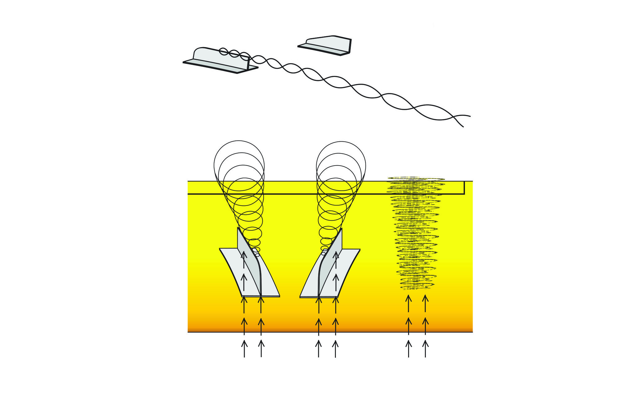
Figure 6: VGs are positioned obliquely (10° to 20°) so that they have an angle of attack with respect to the oncoming airflow (causing the airflow to spill over each VG and form the highly energized vortex).
When the goal is strictly to improve aileron authority, the VGs are installed roughly 1 to 3 inches in front of the hingeline on the top and bottom of the wing in front of the ailerons.
The tradeoff for utilizing traditional fin VGs is approximately 1% reduction in top speed, but more practically, they make the wing harder to clean and are prone to being knocked off.
The contemporary solution, increasingly seen on modern aircraft, is to use flat triangle VGs instead (Figure 7). Although this style of VG is typically made from thin, clear plastic on full-scale aircraft, the author cuts his flat triangle VGs out of thicker 3/32 thick balsa and secures them with clear GOOP contact adhesive for best results.
Image
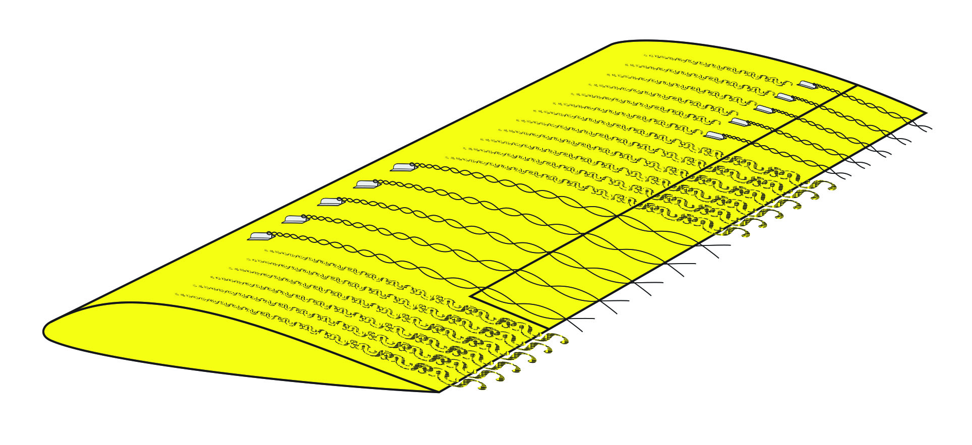
Figure 7: VGs positioned in front of the ailerons on the top and bottom of the wing reenergize the airflow over the ailerons to maximize control authority and generate a linear control response.
Although optimizing control of the wing is important, VGs are sometimes also installed on the horizontal and vertical tails to improve elevator and rudder effectiveness and achieve a more linear response. VGs are also quite effective on the turtledeck, in front of the vertical stabilizer, to help reduce the annoying tail waggle resulting from the turbulent boundary layer, hinge slop, and slop in the rudder servo.
Image
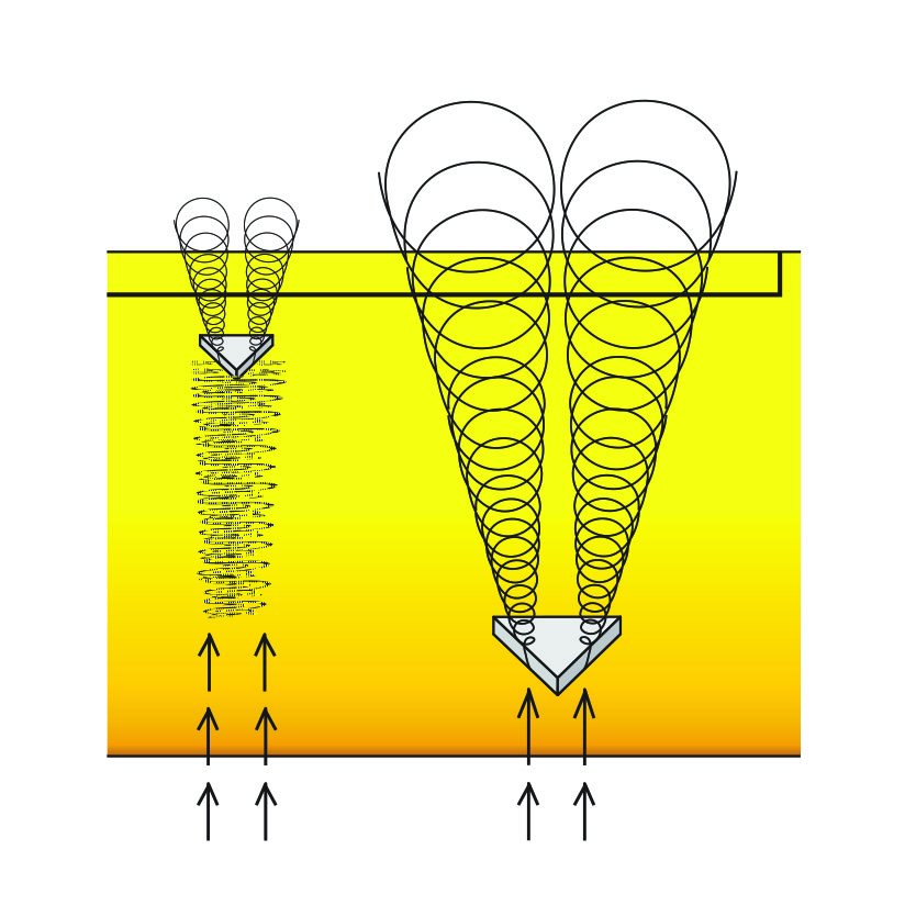
Figure 8: VGs installed along the LE energize the airflow over the wing to delay separation (stall)and improve aileron authority.
Conclusion
The 1st U.S. R/C Flight School programs are predicated on a belief that one improvement is only that—yet several improvements can have a significant impact! Hence, thicker control surfaces and/or VGs are utilized on every airplane in the flight school training fleet to improve each pilot’s ability to maintain positive control at slow speeds or in wind, as well as to tame the tip-stall tendencies of certain models.
Most important, thicker control surfaces and VGs make training more consistent, and therefore more enjoyable for both student and teacher, by ensuring the in-flight results more closely follow the pilot’s intentions.
The major drawback is that once you’ve experienced the solid control feel they provide, you’ll never again be satisfied with conventional handling! Happy flying!
Dave Scott is a champion full-scale aerobatics competitor, air show pilot, aviation author, and he operates 1st U.S. R/C Flight School. His manuals and articles feature the specialized training techniques that he has developed—instructing more than 1,700 RC pilots of all skill levels and setting up and test-flying more than 1,000 airplanes at his school. More information about Dave’s books and school can be found at www.rcflightschool.com.


Comments
Vortex Generators
Excellent article...
Thanks !!
Thicker Control Surfaces and Vortex Generators Explained
Great article! Just go to show you constantly learn new techniques and applied aerodynamic fixes to bad or poorly designed aircraft. Thanks!
Excellent article. I was
Excellent article. I was always wondering what was those little triangles in some real airliners wings.
Thicker Control Surfaces Explained
Very good article, detailed enough without getting too technical. Wish you had included blunt or squared off control surface trailing edges, though that may have expanded article beyond desired scope.
Add new comment