01. In flight, the Whynott is solid and stable and flies in a nice, gentle circle. With 1,000 winds on a 20-inch loop of 3/16-inch Tan rubber, the model makes consistent, 40-plussecond flights in calm air.I’ve dabbled in Free Flight (FF) for many years, but as time marched on, modeling endeavors gave way to Control Line and eventually RC. During those pursuits, FF fell by the wayside, although I never lost my desire to chase those little rubber-powered models, hopping from one thermal to the next across the prairie. After years of inactivity, the bug bit again and I decided to have another go at FF.
My goal was to design a simple Sport model that would be quick and easy to build, could deliver flight durations of a minute or so in calm air, and could be flown at smaller fields. With no preconceived notions of what the new design should look like, I simply sat down and laid out a three-view outline that "looked about right."
When the tweaking was done, the structure was filled in and it was time to build. The result was Whynott.
Construction is simple, incorporating only a small number of shaped parts to keep building quick and easy. Basic construction is from bits of 1/16-, 1/20- (optional), 3/32-, and 3/16-inch sheet and 3/32-inch square balsa with a few standard sizes sprinkled in where needed. Covering and trim was done with Japanese tissue and dope. The result is a worthy little Sport flyer with a ton of potential for those with larger flying venues.
Framing the Model
Begin by cutting out the parts from the appropriate wood sizes using the provided patterns. In an attempt to keep the flying weight to a minimum, ribs R2, R3, and R4 were cut from 1/20-inch balsa, although 1/16-inch balsa could be substituted with no ill effects.
Construction begins with the vertical and horizontal stabilizers. The frames are built directly over the plans using part DF and 3/32-inch square balsa. When completed, lift the frames from the board and sand to shape. Bend the tailskid from .025-inch steel wire, fit it into the rudder, and glue it in place.
The fuselage side frames are also built directly over the plans. Pin MPS in place and build the right-side frame around it. Fit the 1/16-inch balsa fill at the front, flush against the building board. The left-side frame is built the same way, but with the balsa fill flush with the top edge of the frame.
To join the frames, pin the 3/32 × 3/16-inch balsa header in place over the plans along with the two 3/32-inch square balsa crosspieces at the wing saddle. Pin the side frames upside down over the plans, align them vertically, and glue the crosspieces in place. Add the bottom crosspieces in the cabin area. Pull the tail post together, glue it, then add the remaining crosspieces aft of the cabin.
Moving forward, fit and glue the bottom front crosspieces in place. Remove the frame from the board and add formers 1 through 4 and the 1/16-square-inch balsa stringers. Bend the landing gear to shape from .032-inch steel wire. Sandwich the landing gear between the two landing gear mounts. Dry-align and glue the assembly into the fuselage frame. Sand the completed frame to its final shape.
The outer wing panels are built directly over the plans. Begin by pinning the 1/32-, 1/16-, and 3/32-inch balsa shims in place over the plans at the locations shown. Pin the 1/16-square-inch balsa bottom span- wise spars in place then align and glue the ribs in place on the spars. Align and glue the 1/8 × 1/4-inch balsa leading edge (LE) and the 1/16 × 1/8-inch balsa trailing edge (TE) in place followed by the top span-wise spars.
Image
02. The built-up fuselage and tail group are primarily from 3/32-squareinch balsa.
Image
03. With the frames joined, the front formers and stringers are glued in place to complete the fuselage frame.
Image
04. When the fuselage assembly is completed, the frame is sanded to final shape and set aside to await the covering.
Image
05. Because of the tapered wing, platform shims under the three outboard end ribs are required to build in the slight angle at the bottom of the outer wing panel.
Image
06. The bottom spars are pinned in place on the shims then the ribs are glued in place.
Image
07. After adding the LE, TE, and top spars, the wing panel is complete and ready to be joined at the center section.
Image
08. The second wing panel is built up and the panels are ready to be joined.
Image
09. The wing panels are joined at the center by blocking up the wingtips and gluing in sections of the upper and lower spars and the addition of the LEs and TEs.
Unpin the wing panels, prop the wingtips up 1-1/4 inches from the board, and pin it back in place. Add the 1/16-squareinch balsa top and bottom spars and LEs and TEs at the center section and glue them in place. Finally, add the 1/16-inch balsa gussets at the TE then sand the wing to final shape.
Covering the Model
Perform a final detail sanding to remove any remaining bumps and boo-boos then give the frame three coats of nitrate dope. Cover the model with Japanese tissue, mist water on it to shrink it, and give it a brushed coat of thinned nitrate dope to seal the tissue. Add trim tissue followed by a second coat of dope.
Image
10. The completed wing assembly has been sanded to shape and is ready for covering.
Image
11. The Japanese tissue covering is applied using three coats of nitrate dope on the frame to attach it. The tissue is shrunk taut by applying a light mist of water sprayed from an airbrush.
Image
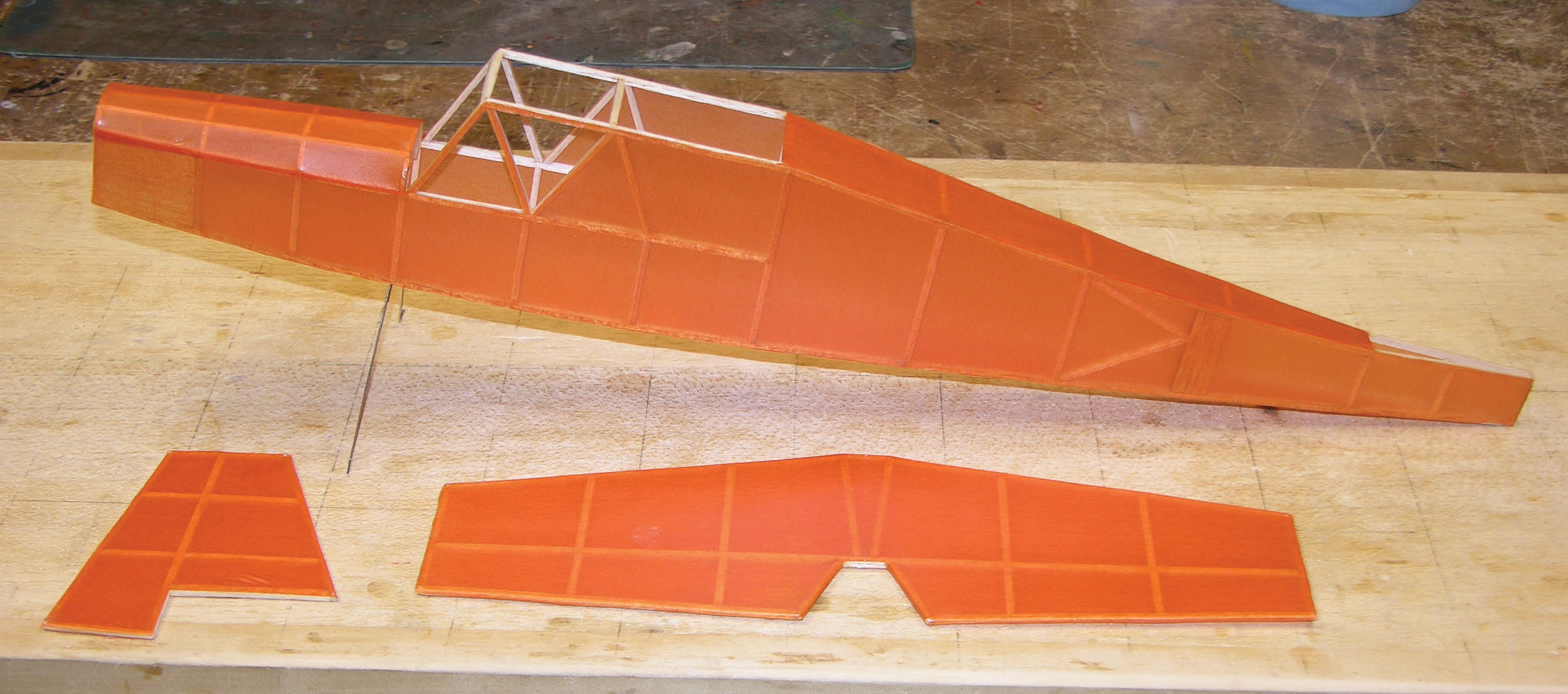
12. The fuselage is covered using the same techniques as the wing and tail section.
Image
13. With all of the covering in place on the wing, the tissue was sprayed with water to shrink the covering. To prevent warping, the panels were pinned to the board using shims until the shrinking process was complete.
Image
14. The nose block was built-up according to the assembly drawings then hand-fitted to insert snugly into the fuselage frame.15. The entire model was given a brushed coat of thinned nitrate dope. The trim was doped in place then a second coat of nitrate dope was applied.
The nose block is built up according to the provided detail drawings. The block was drilled for 3° down and 1° of right thrust and fitted into the fuselage. The wheels are cut from 3/16-inch balsa, and a 1/16-inch outside-diameter (OD) aluminum tube axle bushing is glued in place. To mount the wheels, I slipped them onto the axle. The axle needs to be pinched with a side cutter to distort it enough that the wheels won’t slide off.
The windshield and side windows are cut from a .004-inch acetate sheet and glued in place. Align and glue the wing in place. Using the wing for reference, align and glue the tail section in place. Finally, make up the 20-inch rubber loop from 3/16-inch Tan rubber and secure it in the fuselage at the rear with the 5/32-inch OD aluminum tube. With that, the model is complete.
Trimming the Model
I flight-trimmed my model using the 20-inch single loop of 3/16-inch Tan rubber. The rubber was wound 200 turns and allowed to unwind completely. I trimmed the model for glide, which required only a small amount of clay on the tail. The center of gravity turned out to be 2-3/8 inches (60%) from the LE (at the root). The first two powered flights were made with 400 and 600 turns.
I usually trim my models for a left turn in power, but Whynott really wanted to turn right. The initial circle was too wide for such a small flying field, so I added a small drag tab made from Scotch Brand tape to the right wing.
The third and fourth flights were made with 600 turns, which produced a nice, shallow climb and a good right-hand circling pattern. From there, I wound the rubber to 800 turns, producing solid 30-plus-second flights. With 1,000 turns, 45- to 50-second flights became the norm.
Image
16. The side windows were glued in place. When they were dry, the windshield was attached. Masking tape held the windshield in place while the glue dried.
Image
17. With all of the covering and trim in place and doped, the wing and tail section was glued in place and the finishing touches were added to complete the model.
Image
18. The covering was removed from the bottom of the fuselage at the motor peg. The open panel has no effect on the model’s performance and makes installing the rubber motor much easier.
Image
19. From the rear, you can see the relatively long tail moment and generous vertical and horizontal stabilizers that contribute to the model’s overall stability.
And with that, the model is ready for some good, old-fashioned sport flying on calm summer days. I know the Whynott has a lot more potential, but most flying sites are limited in size and there isn’t room to go much beyond a flight duration of more than a minute or so.
For a model designed for small fields, Whynott is easy to build, easy to trim, and a worthy little flyer.
By Louis Joyner | [email protected] As seen in the October 2022 issue of Model Aviation. WHY WOULD ANYONE DO THAT? There are hundreds of full-size Free Flight (FF) plans that are available from
Free Flight Scale By Tom Hallman | [email protected] As seen in the March 2023 issue of Model Aviation. WHEN I FIRST started flying rubber-powered Free Flight (FF) in 1987, I had no idea
Thank you for a great build article. I have been longing to build a free flight model for some time and this is the one that will get me started.
Almost every model in my hanger is built from plans. Taking a stack of wood and cutting, fitting, and gluing it into a flying model is extremely rewarding.
With our local hobby store gone and with the next closest one failing to replace inventory, I am having difficulty getting building supplies. Wood isn't a problem, it's all the other bits that take extra effort to locate. It's costly and time consuming.
Sorry for the rant, it's just frustrating that there isn't a one stop shop that has everything in stock anymore.
I saw the WHYNOTT in MA and decided to "get back to basics" and build one.
When i cut out the parts I made 2 sets. It's just as easy to make 2 sets as one.
I have the first air frame completed and ready to cover.
Currently looking for instructions on covering - it's been about 65 years since I last covered a model with tissue.
Thanks to Pat Tritle for designing and publishing the WHYNOTT.


Comments
Whynott and other scratch built models
Thank you for a great build article. I have been longing to build a free flight model for some time and this is the one that will get me started.
Almost every model in my hanger is built from plans. Taking a stack of wood and cutting, fitting, and gluing it into a flying model is extremely rewarding.
With our local hobby store gone and with the next closest one failing to replace inventory, I am having difficulty getting building supplies. Wood isn't a problem, it's all the other bits that take extra effort to locate. It's costly and time consuming.
Sorry for the rant, it's just frustrating that there isn't a one stop shop that has everything in stock anymore.
Whynott
I saw the WHYNOTT in MA and decided to "get back to basics" and build one.
When i cut out the parts I made 2 sets. It's just as easy to make 2 sets as one.
I have the first air frame completed and ready to cover.
Currently looking for instructions on covering - it's been about 65 years since I last covered a model with tissue.
Thanks to Pat Tritle for designing and publishing the WHYNOTT.
Add new comment