
Written and designed by Luther Hux Read the entire plans-build article. Find the entire feature on page 70 in the September 1981 issue.
"RIGHT ON," Time magazine reported, and right on it was. The success of the shuttle program carried an air of excitement.
Image

Shuttle and Snapshot Twin look made for each other, although we'd expect a 747 carrier plane. Snapshot works just fine- Luther's home too small for a 747I had considered an RC model of the shuttle to ride on Snapshot Twin ever since the Twin was completed. The cargo-carrying appearance made Snapshot Twin a natural for the shuttle, in spit of the fact that a 747 was the actual aircraft used.The project remained just a few sketches until the excitement of the landing set the idea in motion. The next morning I went to the gift shop at Goddard Space Flight Center for information and a model kit. I also purchased a patch for the flight like the one worn by the crew. By that evening the sketches of the Shuttle were being transferred into construction drawings. Since the prime use of the model would be for the show team I belong to, I used a very hefty balsa construction that could survive a hard landing and be ready for the next show. one team member nicknamed it the Flying Armadillo. However, by using very light balsa and by hollowing out all the blocks, the unpainted empty weight was only 3.5 oz.Once the basic model was completed, I could no longer contain my curiosity. Would it fly like an airplane or a brick? I had heard a lot about the glide of the full-scale Shuttle. The raw balsa nose section was wrapped with foam rubber to protect my hard work, and the fuselage doors were taped shut. Then I went out to the front yard to see if it would perform. The front yard was a perfect test ground, as I had not mowed the grass recently. The tall grass would help cushion the landings ...or crashes.The model took flight. The guessed-at center of gravity (CG) seemed to be perfect, and the model would settle in for a beautiful landing every time. Well, most every time. I had expected a deadly sink with the small wings, but found it would glide all the way to a distant tree. It definitely put that foam padding to work. Since there is nothing to hold to land the model, some of the launches were terrible, but the Shuttle corrected the bad angles and settled in for level landings.
Image

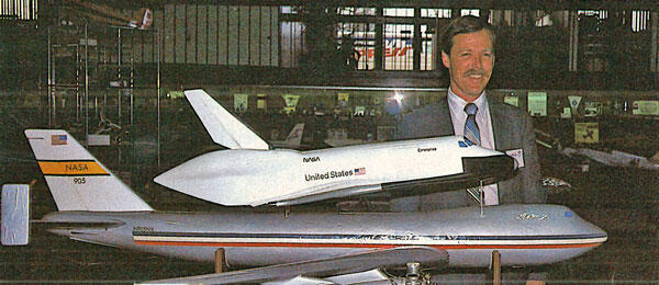
Author's wife, Dawn, shows off the Shuttle infront of the 16-ft. model at the National Airand Space Museum. RC Shuttle is 1/72 scale.The finished model (equipped with a moderately light radio) had a fast and realistically steep glide angle, so I could not recommend front yard hand launching past the raw balsa stage. The 1/72 scale shown in the drawings can be carried aloft by a Falcon 56 using the larger recommended engine. A one-and-a-half size to double size could be carried by a Sr. Falcon or similar model. The larger size is best for the less experienced pilot, since the lighter wing loading would reduce the speed and glide angle. I would not recommend the smaller Shuttle to a novice, because it is a handful-requiring quick decisions and careful response. An ultra-light radio could allow reasonable sport flying performance with the smaller Shuttle.
Image

Image

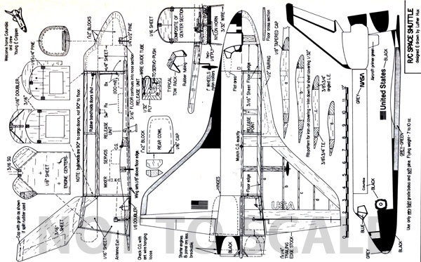
The interior layout. Note that receiver and battery covers have been removed to save weight. Cut weight when you can-sink rate is fast enough as it is. A homemade mixer is installed between the servos and elevons. Move the receiver forward or backward for balancing-no ballast weight is wanted. Author uses a Royal receiver and Ace servos.I recommend the use of a plastic kit as a guide in shaping the carved portions of the Shuttle. For your paint markings, use the photos in Time magazine. The Columbia has a few changes in marking over other drawings and earlier Shuttles: more black on the top of the wing leading edge and more black at the top of the rudder. Most display models show a green-grey leading edge, but the actual phoros appear as grey-take your pick. The plastic kits can provide you with more detail than it would be practical to use on a flying model. The airfoil is a compromise between what would appear scale and still give good performance.Now that we have covered the modifications, let's build the Shuttle. Begin with the fuselage center section. Cut out the bulkheads, but do not cut out the centers until the cross-grain doublers have been attached; the bulkhead is too fragile with the centers removed. Mark the door edge cut lines on both sides of each bulkhead, and cut the door lines halfway through the bulkhead thickness. The final cut through is made after the center is sheeted. Glue the bulkheads to the floor piece with the partial cuts facing inside. Note the angle of the bulkheads to the floor.Glue in the pine longeron sets, trying not to glue the adjacent longerons to each other. The gap between the sets is the hinge line for the doors. Light pine longerons are recommended here instead of balsa to prevent warping of the doors. Wet one side of the sheeting with hot water, and glue the dry side to the frame starting at the top door seam. When dry, cut the sheeting at the gaps between the longerons, and complete the cuts started in the bulkheads to remove the doors. Tape the doors back in place. Attach the 1/16 cross grain doubler to the forward bulkhead, but be careful not to apply glue to the door area. Trim the edges, and mini-saw the cutout from the center of the bulkhead.Assemble blocks of soft balsa from which to cut the nose section. Mark the top and side profile on the blocks, and cut with a band or jigsaw. To keep the blocks square on the table for the second cut, place the nose section back into the scrap that was just cut off, and hold in place while the vertical cut is made. Note that the floor area of the nose section is open and interlocks with the floor of the center section.Draw the bulkhead outline on the back of the trimmed blocks to keep you from carving away too much. Carve and sand away anything that doesn't look like the Shuttle. Use a plastic model and published photos as your guide. Hollow the nose section to about 1\4 in. thickness, and use a high intensity lamp inside the nose to check for thin spots. Glue in the pine bar for installing a nose gear wheel.Glue the nose section in place, and blend the edges with the center section. The flat "temple" areas behind the cockpit windows continues to interrupt the otherwise curved top of the Shuttle right on back into the door area. This creates a thin spot on each door front edge, which must be beefed up with hardwood putty or balsa inside the doors.Glue the rear cross-grain doubler to the rear bulkhead, and trim flu sh. Mark the attachment points of the rudder and rear sections on the rear bulkhead. Mini-saw the cutout from the center of the bulkhead.Cut the rudder from 3/16 sheet, shape it, and glue it in place. Starting with the floor, cut and assemble the 1/16 sheet pentagon-shaped tail section using the marking on the rear bulkhead for alignment. Note that the rear floor is angled up. Cut and fit the engine bulkhead in place, but do not glue at this time. You will need access to this area later. Cut the outline of the rear cowl cheeks from 1 x 2 in. block, and sand to shape. Hollow out the cowls to about liI-in. thickness. Attach the cowls, and sheet the rear of cowls with 1/32 balsa.Now for the wings, to convert our freight car into a glider. Assemble the 3/ 8 x % balsa wing outline flat on the plans. Cut leading edge fairings from !-loin. sheet, and attach. Now you will notice a liI difference between the fairing and the leading edge. Overlay the leading edge with a 3/4 x 1/8 in. strip that tapers to 1/32 at the wing tips. Use a glue that is easily carved and sanded, as most of this strip will be cut away. Hold off on gluing in the ribs if you are using the landing gear. if you are using skids, then glue in all but the ribs adjacent to the fuselage. Installing the landing gear later is different with the ribs in place.Make the center line in the spars, and separate the wings. Trim the center of the wing spars for the dihedral angle and the notch for the floor overlap. Note that the bottom of the wing should be 1/8-in. up from the bottom of the fuselage floor. Don't cut the notch any deeper. The wing and belly of the model will be sanded into a smooth curve that matches the dihedral after the wings are attached, hence the thick floor to accommodate the shaping.Slot the fuselage sides for the spars, and test the spars for dihedral angle and fit. Cut slots for the landing gear spar if you will be using wheels.With the wings in position, note the bevel required on the leading edge fairings to match the dihedral, and sand to fit flush to the fuselage. Do not make final adjustments in your spar notches until the fairings fit correctly.Weight the fuselage down on a table and glue the wings in place with the wing tips supported at the right dihedral angle. Eye the wings carefully to check for any difference in angle of attack in each wing. With a short wing span, this is very important to prevent roll difficulties. The rear floor at the trailing edge spar is only 1/16 sheet, so the rear spar will not sit too high. You could use liI sheet here and notch the spar, but I simply installed doublers around the spar.Drill holes for the wire in the landing gear spar, and glue the spar in place. The bottom outer edges of the L.G. spar should align with the bottom of the wing. Use a straightedge set from leading edge to trailing edge for a guide, and glue doublers and supports around the spar inside the fuselage. Now install the ribs that would have interfered with sliding the L.G. spar in place.The rib outlines on the plans are for iron-on coverings, and if you sheet the top ofthe wing as I did, you must cut the ribs 1/ 32-in. thinner than drawn. I recommend sheeting on the top and fabric for the bottom, as the iron-ons can take more abuse than sheeting and can be retightened when dented. Shape the leading and trailing edges as shown. Note that you have a large strong spar that allows you to produce a good airfoil shape, not just a rounded-off edge. Continue the airfoil shape of the leading edge into the fairing, and smooth the ends of the fairings into the nose section. An emory board is excellent for this.Install torque rods on the elevons. Note that the trailing edge stock is installed " upside down." Install mini-hinges, and shape the elevon tips to match the wing tips. Spot glue the engine bulkhead in place for a final sanding and shaping of the entire model. Don't glue the engine bulkhead in place permanently until the radio has been installed and tested. If you wish to paint the interior, spray a light coat of silver before starting the radio installation. Attach the cargo doors with mini-hinges or fabric hinges.Seal the exterior of the model with sanding sealer. Keep in mind that the surface of the full-scale Shuttle was textured, and hold back on excessive coats of sealer and paint that will add a lot of weight. Apply the white to the top of the model first, and then mask for the large black areas. For scale appearance use satin finish paints instead of gloss or flat finishes . Another good covering combination is white Permagloss Coverite and black satin polyurethane paint. This has a realistic appearance. Doing more than the wings with iron-ons on a small unusually shaped model is a bit of a challenge.
Image

The paint schemes of these two unique flying machines almost match-look at the noses! High stab on the Twin is to allow a drag chute to be released out of a hatch on the fuselage.Mask off the windshield and spray with transparent blue. Then paint in the Lone Ranger mask around the cockpit along with the other black trim detail. For the final touch, borrow the decals from the plastic kit (that I have been trying to sell you) or take your best shot at free-hand lettering. Complete the model with nylon skids or Williams Brothers I-in. wheels.For your radio installation, you can buy or make an elevon mixer for the Shuttle. For the lightest model, the transmitter mixer is best. I was not able to afford another radio for the Shuttle, even though I would like to have used a subminiature like the Cannon. With an average small radio the weight is acceptable. Don't try the small Shuttle with the larger servos and battery. The flying weight musl be under to ounces if you want to enjoy flying the Shuttle. Mine is only 8.9 ounces. By comparing the size of this shuttle to the first RC Space Shuttle used by NASA for release testing, the approximate scale weight of this model would be just under two pounds. Please don't try it, as it's fast enough as it is. Remember, flying is supposed to be fun.
Image

The tall wire launch frame was meant to ensure that the Shuttle would clear the tail of the carrier plane. It didn't turn out to be a problem; a shorter frame would also work well.The launch frame is made of wire and designed to plug in with the wing bolts or strap on with plenty of extra rubberbands along with the wings. For a Sr. Falcon or similar installation simply have the base of the wire frame follow the leading and trailing edges of the wing, and run the rubberbands through the wire frame . Use rubber tubing to cushion where the wire contacts the wing, and be sure to route the wire along the solid portions of the wing and not where it has been sheeted. The top plate is plywood, epoxied and wrapped with fabric reinforcements. The release tab is a nylon control hom. This system has worked well on my RC parachutist for over two years. The push-out spring-loaded release pin allows for attaching and removing the Shuttle without the need for the transmitter.The plate is covered with enough foam to keep a gentle pressure on the Shuttle. The foam only cushions the Shuttle's ride; it is not used to force the Shuttle away from the plate. Too much pressure, and the servo will have trouble releasing the model.The Shuttle should ride at a 3?? up angle as compared to the level flight of the carrying model. This gives the Shuttle the necessary force to pop up and away at release without unnecessary stress on the model during flight. I have worked with a number of release ideas, but the simplest works the best. Climbing creates G forces, and diving puts the tail higher than the Shuttle. The worst system for the models would be to stall, as there is nothing to make the Shuttle separate.The usual procedure is to simply chop the throttle in level flight, and release the Shuttle about two seconds later. At that point both models are coasting equally, and there is plenty of air speed to lift the Shuttle off. By coasting you prevent the carrying model from flying its tail section into the Shuttle before the Shuttle can get altitude. Trying to get a quick pop-up with springs will only bind the servo. Any other release incentives are completely unnecessary.
Image

Snapshot Twin lifts Shuttle for first flight. Luther recommends that the two RC systems be on different bands. If receivers on the same band are too close together, they will cause trouble. Photos by Dawn and Luther Hux.For your first flight, be sure to match the CG perfectly, and get plenty of altitude to allow yourself some time to learn how the Shuttle handles. Don't make sharp turns; the flights only last about 30 seconds, and with steep turns they are a lot shorter.Good luck on your first mission.
Meet the commander of the Columbia and AMA Ambassador, Hoot Gibson.
Order Plans
Image
Image


Comments
RC space shuttle
Hello, I am interested in build a space shuttle for radio control do you know how can I gent the plans to make it happen? I am from Mexico.
Best Regards
Shuttle Plans
I have flown this model...
She was no dream to fly but always fun and entertaining. Never get into a sustained vertical dive, never let it be tail heavy. both of these end badly. from a high launch I rarely had more than 60 seconds from launch to touchdown. I say this all from my experience flying this aircraft 30 times or so before it was retired. Lighter is better too, a real shuttle would weigh over 200 lbs. You want 20-30 oz.
What an akward model!
I am really amazed by this awkward model. You tend so see some RC auto gyros around or maybe even an asymmetrical plane like the Blohm & Voss BV 141, but a Space shuttle is something really special. Wouldn't the plan also suffice to make a depron version of the RC model? @ Jeffry Faleo: Do you have any advice on the mixing? I suppose in 1981 it was done the mechanical way.... All in all, a great article on a fantastic modelling topic!
Add new comment