
Written by Paul Kohlmann and Derek Micko
Scratch-building and flying opposing aircraft, Part 2
As seen in the October 2021 issue of Model Aviation.
Order Plans from AMA Plans Service
Image
Image
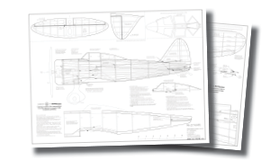
DOWNLOAD FREE PLANS!
Full-size plansTiled plans
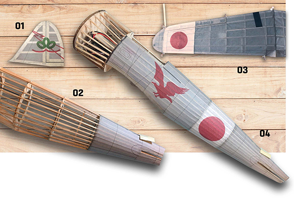
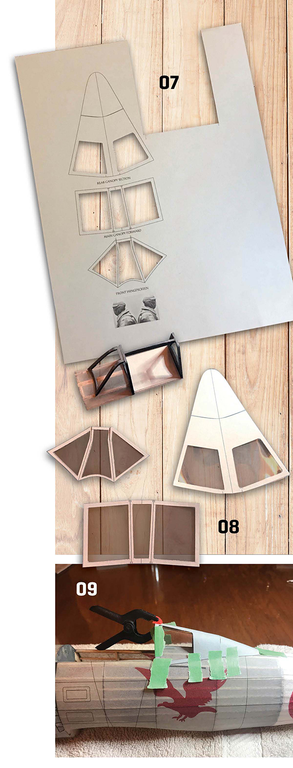
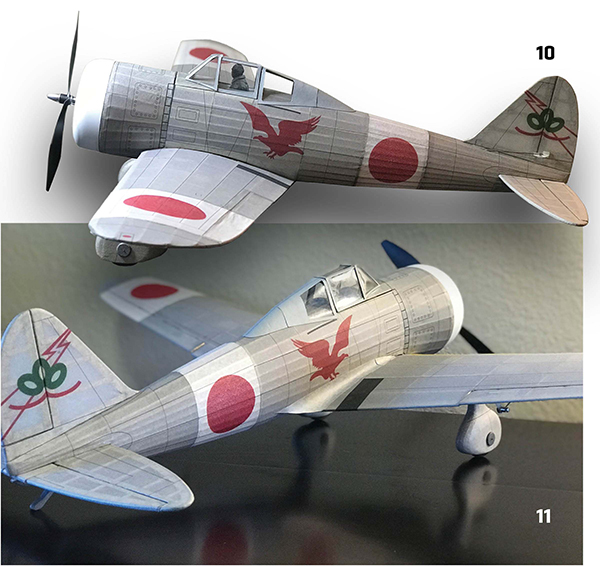
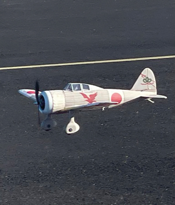
Ki-27 Nate: In last month’s article, I covered the history of the full-scale Nate and the primary construction process. In this article, I will address covering, finishing, and flying the model. The next major step was to cover the model. Usually, I would turn to a lightweight film, but recently, I have been trying printed tissue and I really like the results. Printed tissue has been popular with Free Flight modelers, and a great reference can be found on Paul Bradley’s website (see "Techniques and References" in the "Sources" list). I also created a "how-to" video on YouTube called "FSM Printing on tissue Ki 27 Nate." The video details the entire process, including how to design your printed sheets. Because the plans also include the sheets with which to print your own tissue, I will focus mainly on printing and application.
Image

Image
Image
Image


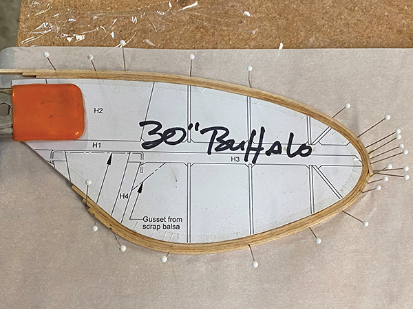
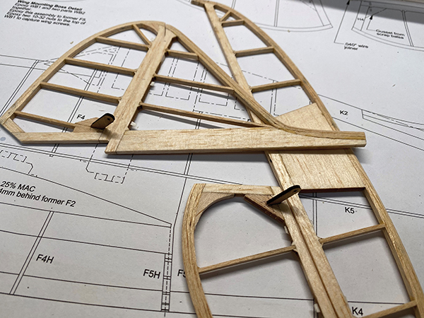
Tail Group Laminations
Begin the tail group by making forms for the laminated outlines. You can either print the tail group parts from the downloadable plans or trace the outline from your kit’s hard copy. Either way, use the inside line from the outline for the form’s template. Attach the template to the form material of your choice. I used 3M 77 spray adhesive to attach the plans paper to a 1/4-inch fiberboard panel. That seemed like a good choice until I realized that I couldn’t pin it down to my building board like the foam forms that I normally use. No worries—a pair of large spring clamps held the forms in place while I made the laminations. The edges of the form were covered with packing tape to prevent the laminations from sticking to the fiberboard. Soak 1/8-inch strips of 1/16-inch balsa in water overnight. Test that the strips are flexible before starting the laminations. This tail group is fairly small. Prebending the balsa over a small jar or steam can loosen it. Keep tension on the first strip to avoid kinks in the balsa as it bends around the form. Add pins as you go to keep the strip tight against the form and pushed against the surface of the building board. Put a thin, even layer of glue on one side of the next strip and repeat. Move the pins from the first strip to the second as you go. Do the same for a third strip then set the lamination aside to dry. Carpenter’s glue works great on wet wood and is easily sanded later, but make sure to let the outlines cure completely before unpinning them so that they hold their shape and don’t delaminate.Framework
Now pin the outlines to the plans. Build up the inner framework by assembling the parts in numerical order. But don’t glue the parting lines for the rudder (parts V1 and V2) and elevators (H2 and H3). After the numbered parts are in place, the bracing can go in. I used a balsa stripper to cut the bracing stock from the edges of the balsa in my kit. Cut each brace slightly large and sand it to the perfect size and shape for its position. Start with the longer braces so that if you get a little overzealous with the sanding, you can take another shot at fitting it in a shorter position. After the last brace goes in and the assembly cures, unpin the tail group parts. Sand a radius in the leading edges (LEs) and a taper at the trailing edges with 60-grit sandpaper. Follow up with a light pass with 220-grit sandpaper. Separate the fin/rudder and horizontal stabilizer/elevators by cutting through the laminated outlines as shown on the plans. Bevel the LEs of the rudder and elevators and these parts are ready to hinge. I used 1/8-inch strips of CA hinge material on all of the control surfaces for my prototype.Image
Image
Image
Image
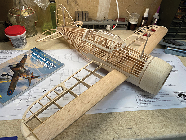
Fuselage
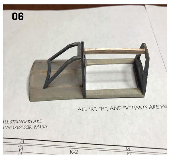
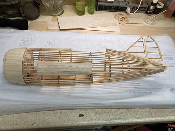
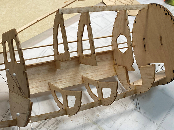
The left side of the fuselage is built over the plans in the old Guillow’s style. Start by gluing and pinning keel parts K1 through K4 to the building board. Formers F2L through F10L are next. Glue these to the keels so that the formers stand perpendicular to the board. The next steps will tie the formers together. Join the formers with side keel K5 then use the left side of the cockpit deck to join formers F5L through F7L. Now add the left wing saddle. Dampen the outer side first so that it curls slightly. Glue the wing saddle to keel F5 and formers F2L through F5L. Now add a few 1/16 × 3/32-inch balsa stringers to stiffen the assembly. Letting the assembly fully cure before unpinning it will help prevent warps in the fuselage. On the right side, unpin the left half of the fuselage and build the right half directly onto the left half. Start by adding the firewall. Preassemble this part by aligning and gluing balsa parts F1A and plywood part F1B. Now glue the firewall to the front keels of the fuselage’s left side. Note that the long motor mount slot goes on the left side of fuselage. Assemble the motor mount as shown in the detail drawing. Make sure that the side panels are in the correct positions. When assembled correctly, the motor will be positioned for the proper downthrust and sidethrust. Epoxy these parts together then fit the motor mount box into the well in the firewall. The belly hatch is next. Glue hatch formers F2H through F5H to keel K4 and the left wing saddle. Be careful not to glue hatch formers F2H or F5H to their respective fuselage formers or it will be difficult to free the hatch later. Now add formers F2R through F10R. Glue each of these parts to their left-hand mates. Use wing pin boss WP to strengthen former F2 and reinforce the wing pin hole. Slide in the battery tray from the hatch side and glue to the firewall and former F2. Preassemble the wing bolt boss from parts WB1 (plywood plate) and WB2 (balsa struts), and then attach it to former F5. Epoxy is a good adhesive for this critical assembly. Now that all of the inner parts are in place, join the right-hand formers with keel K5 and the cockpit deck. Dampen the right-wing saddle as before and attach it to its keel and formers. Complete the fuselage assembly by adding the rest of the stringers. Alternate from side to side and check for twisting as you go.Cowling
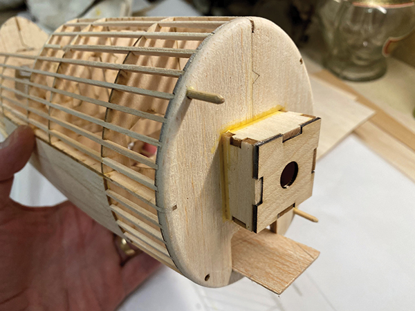
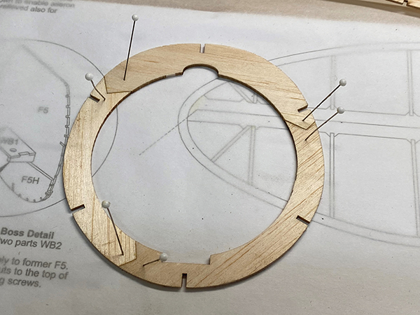
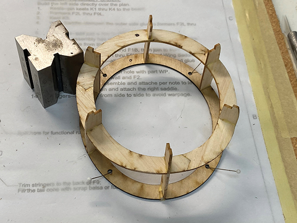
The cowling is built up from a balsa and plywood frame that is planked with balsa. Begin by preassembling balsa cowling formers C2 and C3. Each is composed of three parts to manage the direction of the wood grain. Join these formers and plywood former C1 with cowling keels C4 through C7. Note that there are small alignment holes in parts C1 and C2. They mark the top of these formers. The square cutout in C3 is the top of that part. Use the plans sideview as a template for setting the angles of top and bottom cowling keels C4 and C7. Check that the angle of the sides of the cowling frame is the same from side to side as the assembly cures. Assemble the cowling opening ring from parts C8 through C10. Use the scoop openings to align these parts. Glue this stack to the front of C3. Note that the outside diameter of C3 is smaller than the cowling opening ring. This will make it easier to perch the planks on C3 in the next step.Planking
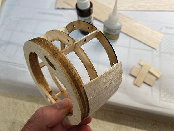
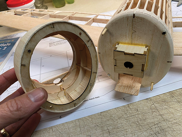
Some builders shy away from planking because it looks tedious. It’s not that bad, especially on a small part such as the Buffalo’s cowling. It also helps that there isn’t much curvature in this cowling, meaning that the shapes of the planks will be simple. Plank the cowling between C1 and C3 with 1/16-inch balsa. Cut 1/2-inch-wide strips for this job. Add a plank to the top of the cowling that covers half of the cowling’s keel C4. Do the same with the bottom and keel C7. Tying the cowling rings and these keels together will make the cowling assembly much more rigid. As with the wing saddle, dampening the outside of the planks will make them curve slightly. Use this to your advantage as each plank is fitted. Place a plank in position to check for tight spots. Sand the plank lightly and fit it again. After a uniform parting line is achieved, glue the plank into position. I generally avoid using CA adhesive, but it works great for this application. A shot of accelerator helps to quickly cement it in place. Alternate the addition of planks from top to bottom and side to side to avoid warping the assembly. Sand the finished cowling with 120-grit sandpaper to knock off the high spots at the edges of the planks. The bottom of the cowling can be fiberglassed for more durability if desired. I expect that my Buffalo will be landing on soft grass, so I skipped this step. The final steps in the cowling assembly are the addition of the attachment hardware. Add two 1/8-inch diameter alignment pins to attach the firewall to the cowling. These can be made from doweling or barbecue skewers. Use two of the four attachment holes that are diagonal from one another. Use the other two holes for pairs of rare earth magnets. An easy way to deal with these is to put a small piece of waxed paper between each magnet pair then epoxy a magnet into each hole in the firewall so that the waxed paper is flush against the firewall’s surface and the second magnet is facing the cowling. After the firewall magnets are secure, fit the cowling over the two magnets. Adjust the cowling magnet hole openings if necessary.Image
Image
Image
Image
Image
Image
Image

Wrapping It Up
That gets us roughly halfway through the build. Next time, we’ll frame the wing, rig the controls, and get some covering on this model. Until then, fly low and build light!SOURCES:
Manzano Laser Works www.manzanolaser.com Park Flyer Plastics (817) 233-1215 www.parkflyerplastics.com Du-Bro (800) 848-9411 www.dubro.com Paul and Ralph Bradley’s Model Airplane Hangout www.parmodels.com FMS Printing on tissue Ki-27 Nate https://youtu.be/1980sL-UJC0 RCGroups Build Thread Park Flyer Fun Scale Ki-27 vs. I.E. Brewster Buffalo https://bitly/39zYm By Paul Kohlmann [email protected] | Derek Micko [email protected]Photos by the authors and as noted


Comments
Nakajima ki 27
Hello
I am Marco an Italian model maker who likes to build, I would like to know if the plans for sale by AMA of the Ki-27 Nate are complete with frames and ribs, because those in download are without ribs and frames.
Thanks
Do the plans include wing
Do the plans include wing ribs and the fuselage formers?
I do not see them in the free plans.
Add new comment